 danjovic
I have added a capacitor to the prototype. I used a 100uF / 16V part because of its diameter (the 47uF part used in debugging was too thick and I ran out of 10uF on my parts bin). The negative terminal was inserted on a hole made with a 0.8 drill bit right above the ground plane but there was no room for the hole of the positive terminal, that ended being soldered on the transistor socket.
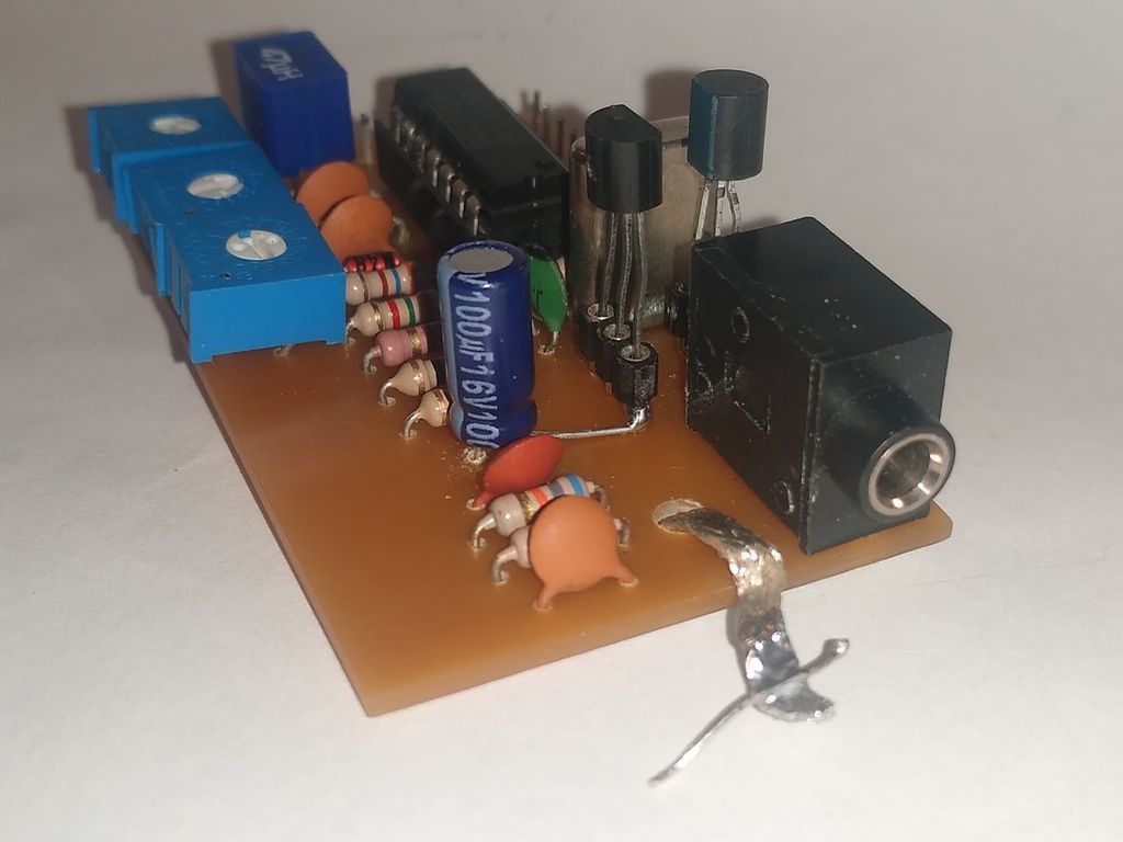
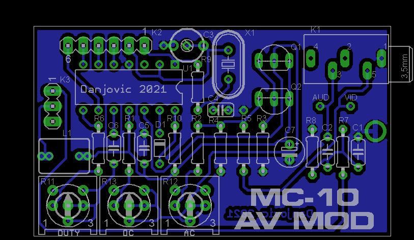
The most recent version of the PCB provides the holes for the bypass capacitor (C7).
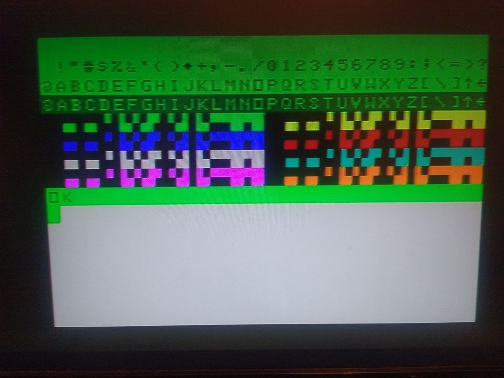
Now I was able to adjust the video signal to an acceptable quality. There is no instructions for this adjustments available on the MC1372 nor on the MC6847 datasheet.
Then I have used the DC offset and AC gain potentiometers to have the video with similar proportions as the NTSC standard. I think I should dig a little more on that, but so far I have the colors with the hues expected (to may eyes).
I removed the transistor sockets and soldered the prototype board on its place.
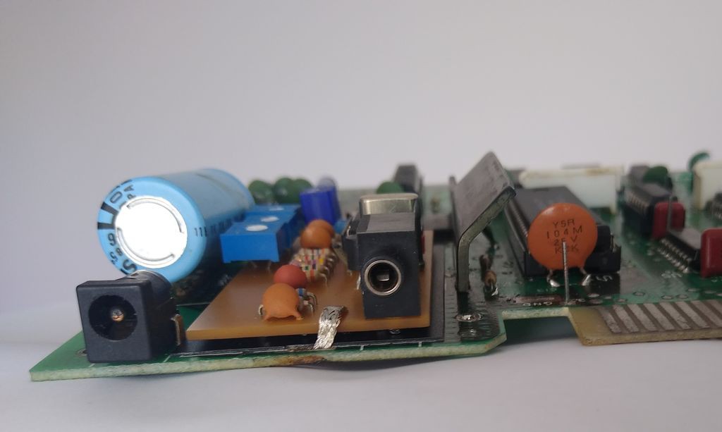
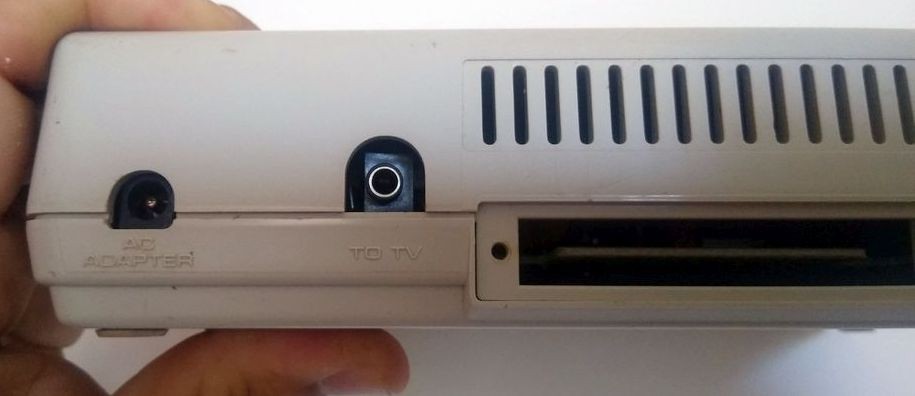
After closing the case the P2 socket was perfectly aligned with the plastic case
Discussions
Become a Hackaday.io Member
Create an account to leave a comment. Already have an account? Log In.