 pcadic
We respect the following steps to solder it in the easy way. The USB A and the buzzer are soldered at the end.
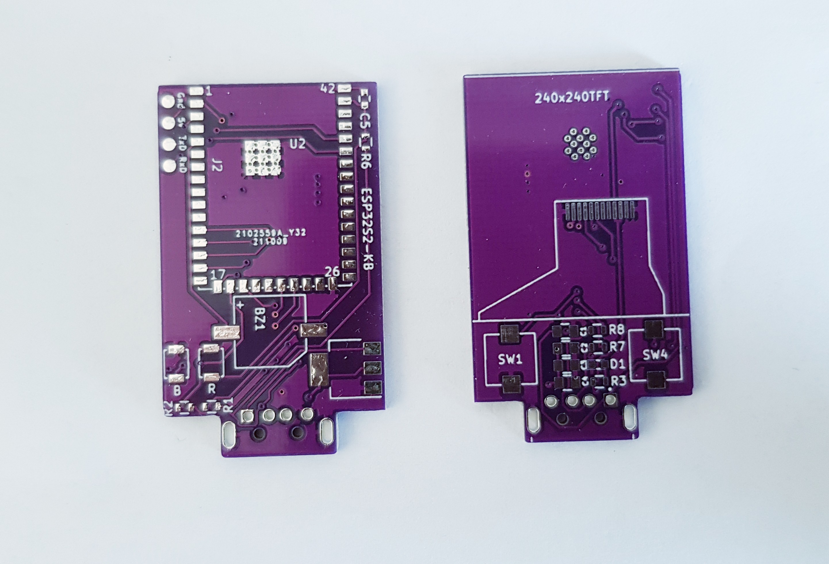
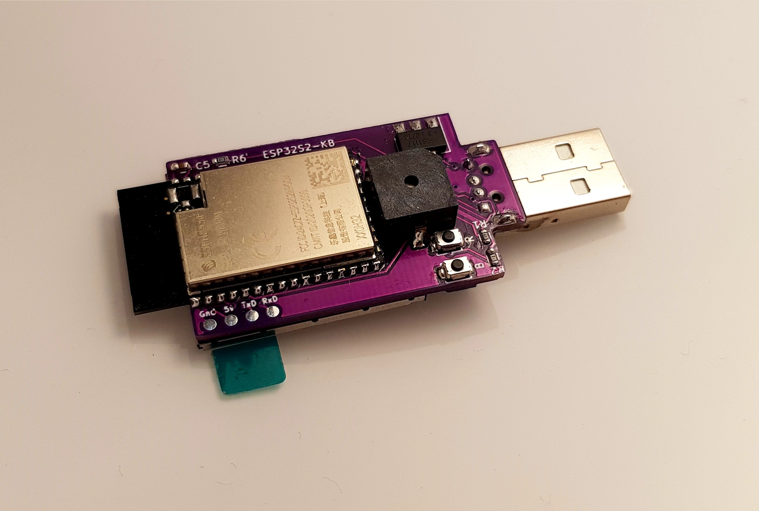
Step 1: Solder the ESP32S2 first using flux and solderr iron. The best option is to put a small qty of solder material on the buttom left line GPIO/PIN, center the ESP32 abd solver this pin. Once positioned we suhhest to solder the top right PIN to block the ESP32S2 in good position. Once set, you can solder all the PINS of the ESP32 (use FLUX+++). We suggest that you place a drop of solder paste on the U2 ground area. You will be able to melt it from the other site with the soldering iron.
Step 2: Solder the voltage regulator, then the 2 B3U-1000P switches, then C5, R6 , R1, R2
Step 3: on the PCB's opposite side, solder C1, C2 , C3, C4 first , then R7 , R8 , D1, R3 (D1 and R3 are optional).
Step 4: melt the ESP32S2 Wroom GND solder paste from this PCB side with flux and solder iron.
Step 5: prepare the Display, position it on the PCB and attach it with tape to avoid any move during soldering. apply a lot of flux on the line of contacts on the PCB. Solder it and take care about not creating shorts between lines. Once soldered, install a 2 sided adhesive tape, remove the tape and rotate/bind the display against the 2 sided adhesive tape. Take care when attaching the display. Try and center it before it touches the tape.
Step 6: Solder the 2 TP1003 buttons. Take care, when you solder them, you should avoid touching the display with the soldering iron to avoid any display damage.
Step 7: Solder the USB A plug. The finish and solder the Buzzer.

Discussions
Become a Hackaday.io Member
Create an account to leave a comment. Already have an account? Log In.