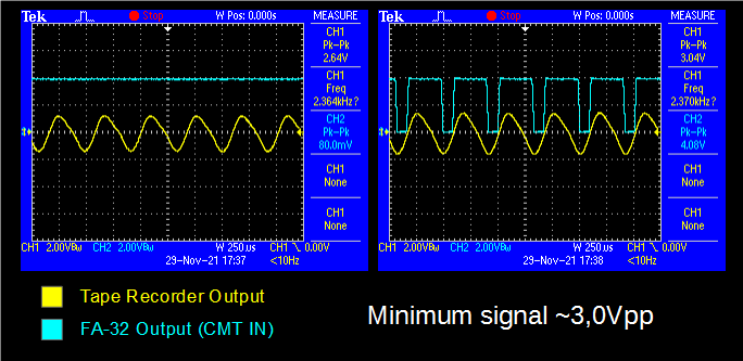
The circuit requires at least 3,0Vpp from an audio signal coming from the tape recorder to detect the pulses

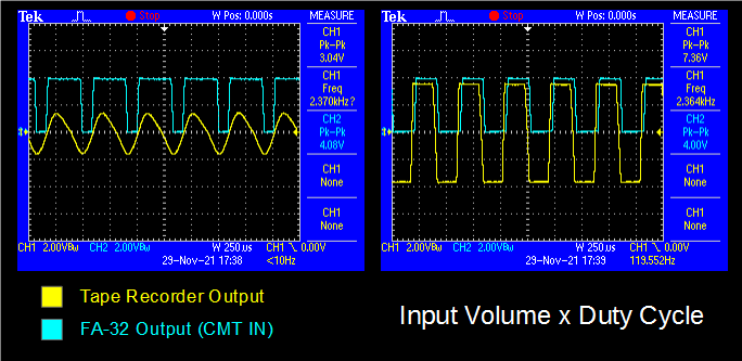
The amplitude of the signal on the input interferes on the duty cycle of the output signal. At the maximum input amplitude the duty cycle is about 50%.

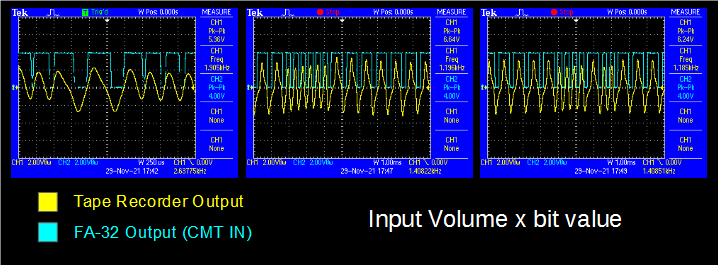
Another noticeable effect is that the amplitude of the signal coming from the cassette is higher during bits 0. That should be related to the frequency response of the magnetic heads and internal (analog) circuitry of the tape recorder.

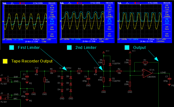
The picture below shows the amplitude of the signals across the circuit.

Last but not least. I have performed my tests using a LM358 instead of the original OP AMP (M5223P) . The MC1358 (or either a MC1458) did not performed well as it is not adequate to operate in single supply.
 danjovic
Discussions
Become a Hackaday.io Member
Create an account to leave a comment. Already have an account? Log In.