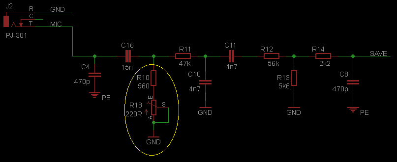
I have inserted one trimpot at the PCB to allow some adjustment on the MIC signal. It is placed in series with the lower resistor of the voltage divider on the output stage.

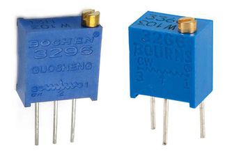
There was not much room for a trimpot without a significant redesign of the board, but it was possible to fit a Bourns 3296 or 3266 series vertical adjustment trimpot.

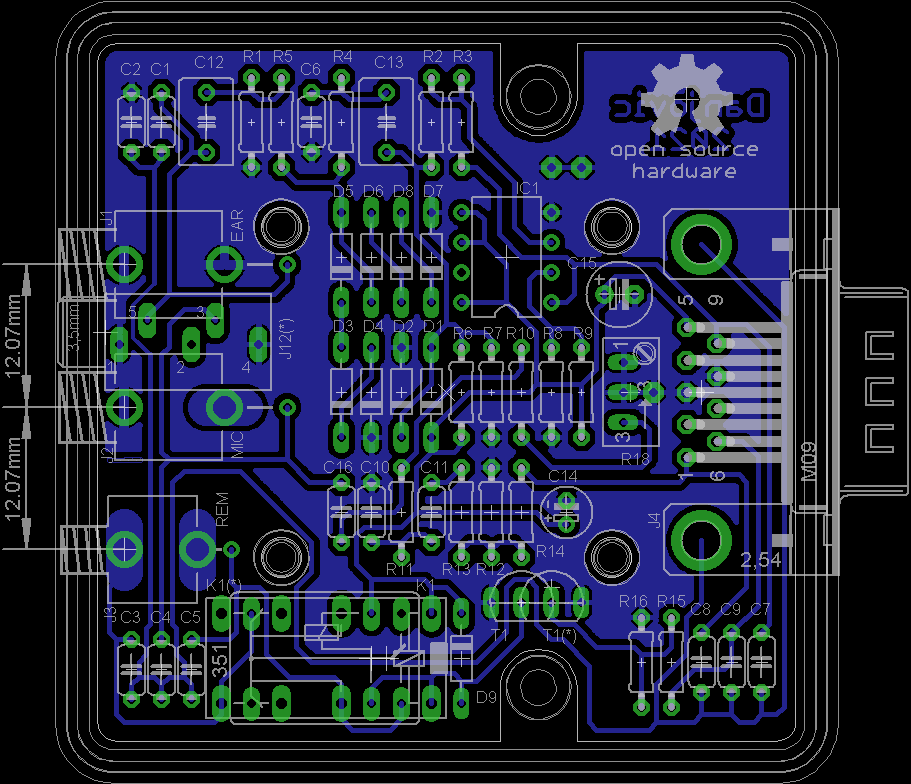
And the layout of the PCB with the added trimpot is shown below. This board also provides more room between the P2 Jacks.

 danjovic
Discussions
Become a Hackaday.io Member
Create an account to leave a comment. Already have an account? Log In.