 Nikola
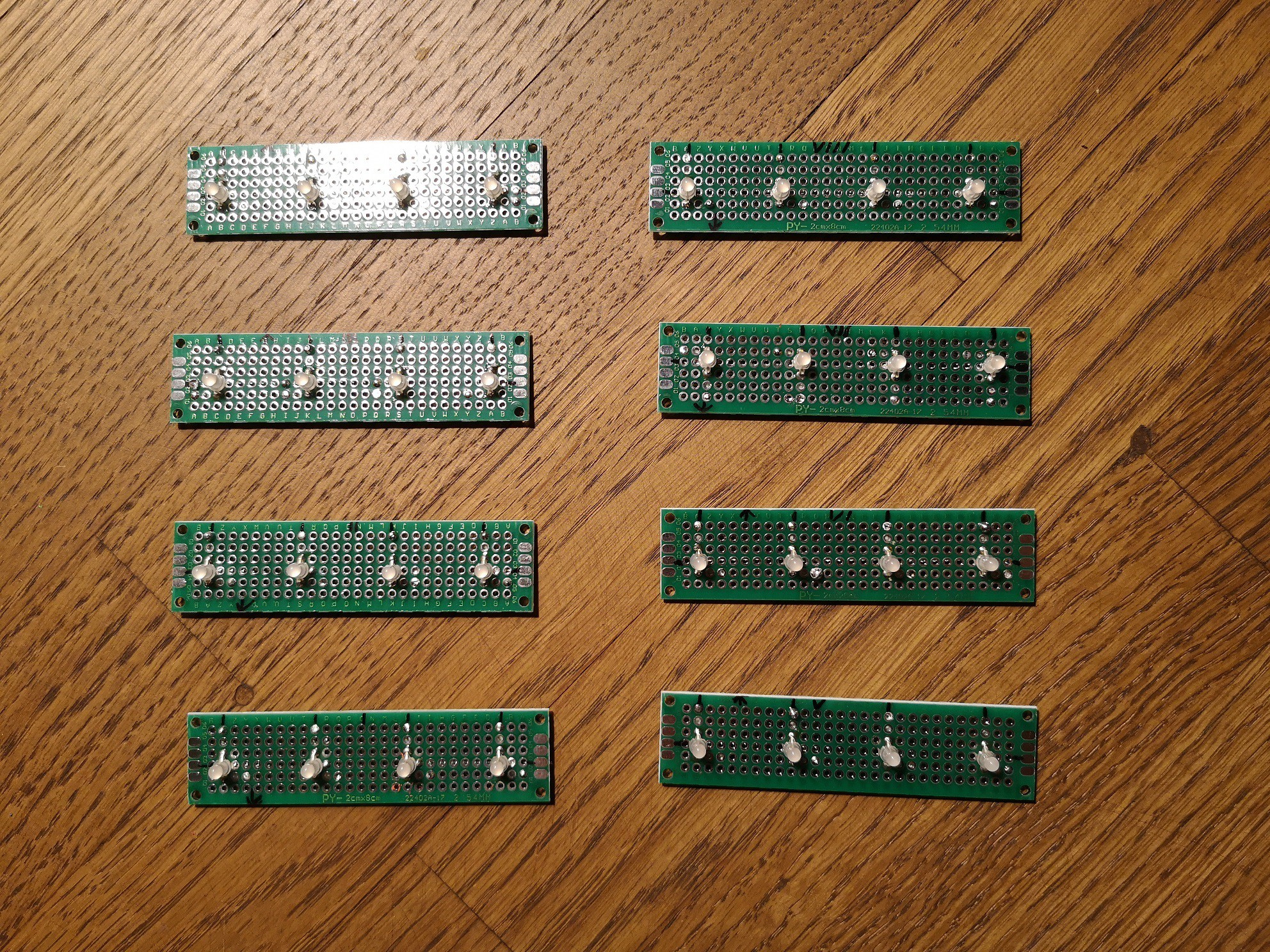
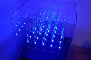
For the LEDs I used bi-color LEDs (red and green). This gives more possibilities for interaction with the toy.
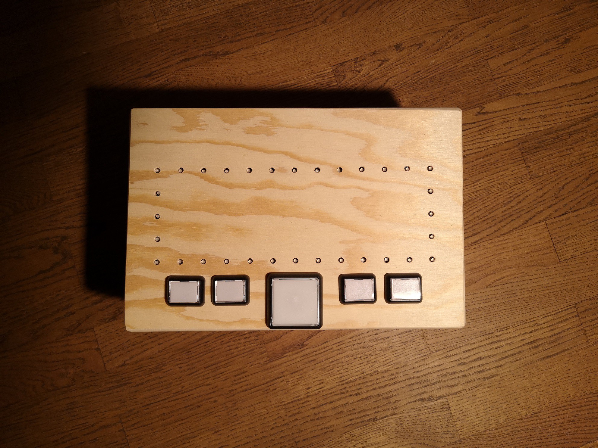
The buttons I used are repurposed from old arcade and gambling machines. They are mechanically robust and should last long. I took a big one as the main button and four small ones. I don’t have an idea what I will do with the four small ones yet, but I wanted to do the hardware part of this project only once. Maybe I will later program “Simon-Says” for them.
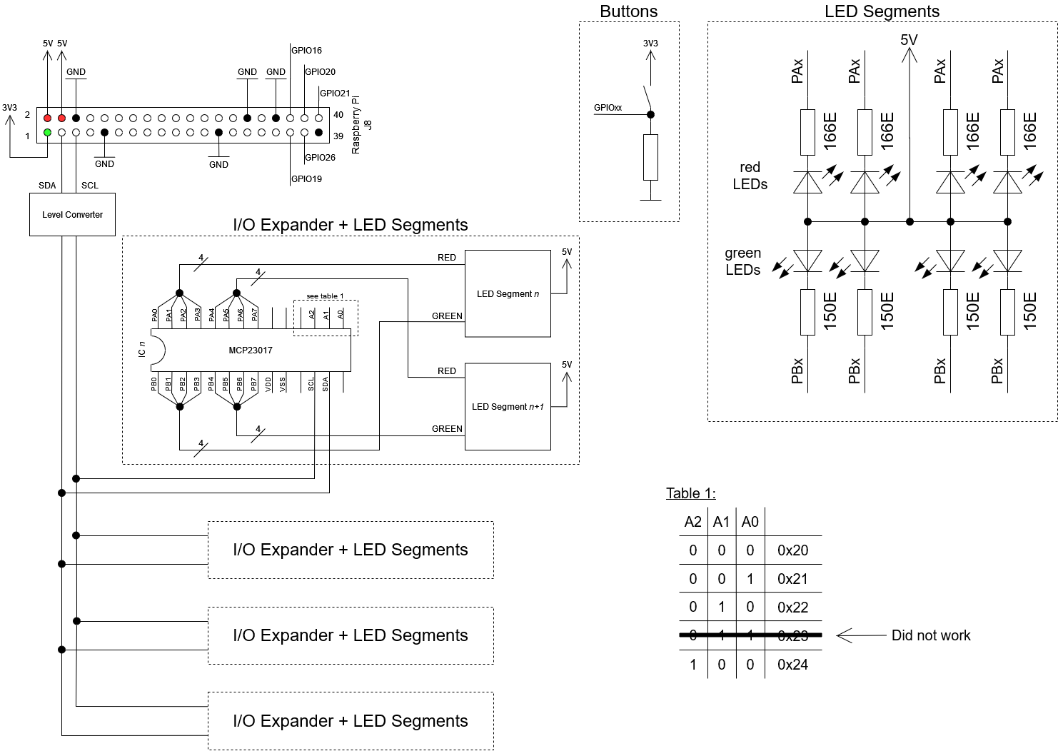
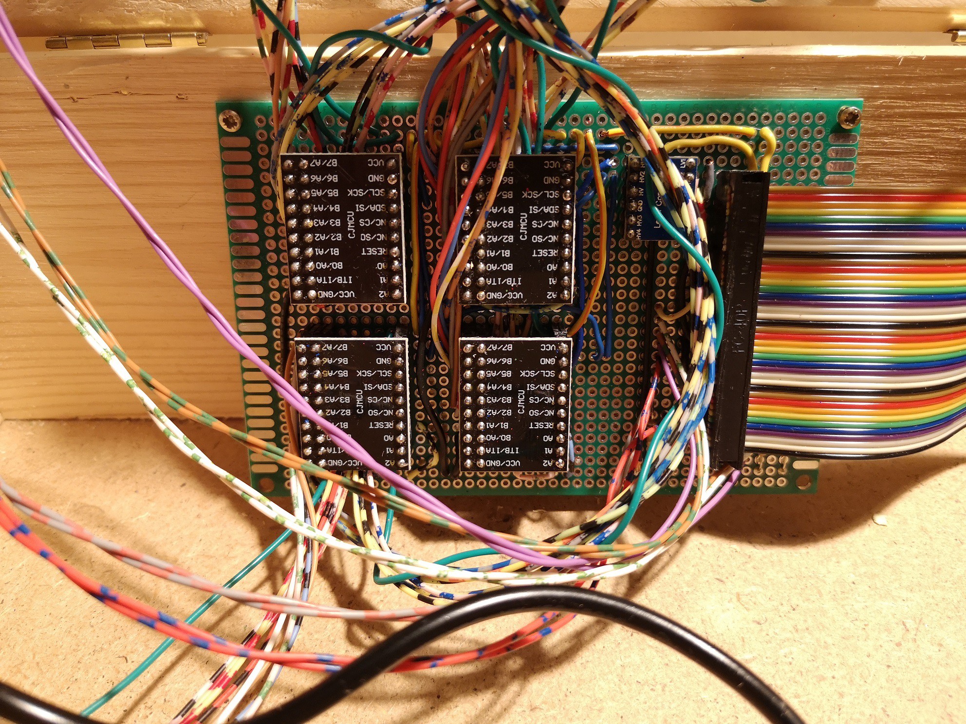
For the computer I chose the Raspberry Pi Zero W. I had one in spare and for these tasks I didn’t need something fancier. The Raspi does not have enough GPIOs to have a decent ring with LEDs. That’s why I used the “MCP23017 I2C I/O Port Expander”. This expander can control 16 GPIO pins and can be controlled via I2C-bus. In the end I used 32 LEDs. This means I needed 64 GPIOs that are controlled by four GPIO expanders. For the red lights I used the A port and for green the B port on every module. I separated the 32 LEDs into 8 segments with 4 LEDs each.
For the power supply I used the 5V pin of the Raspi on the J8 Header. This pin is directly connected to the 5V of the micro-USB connector.
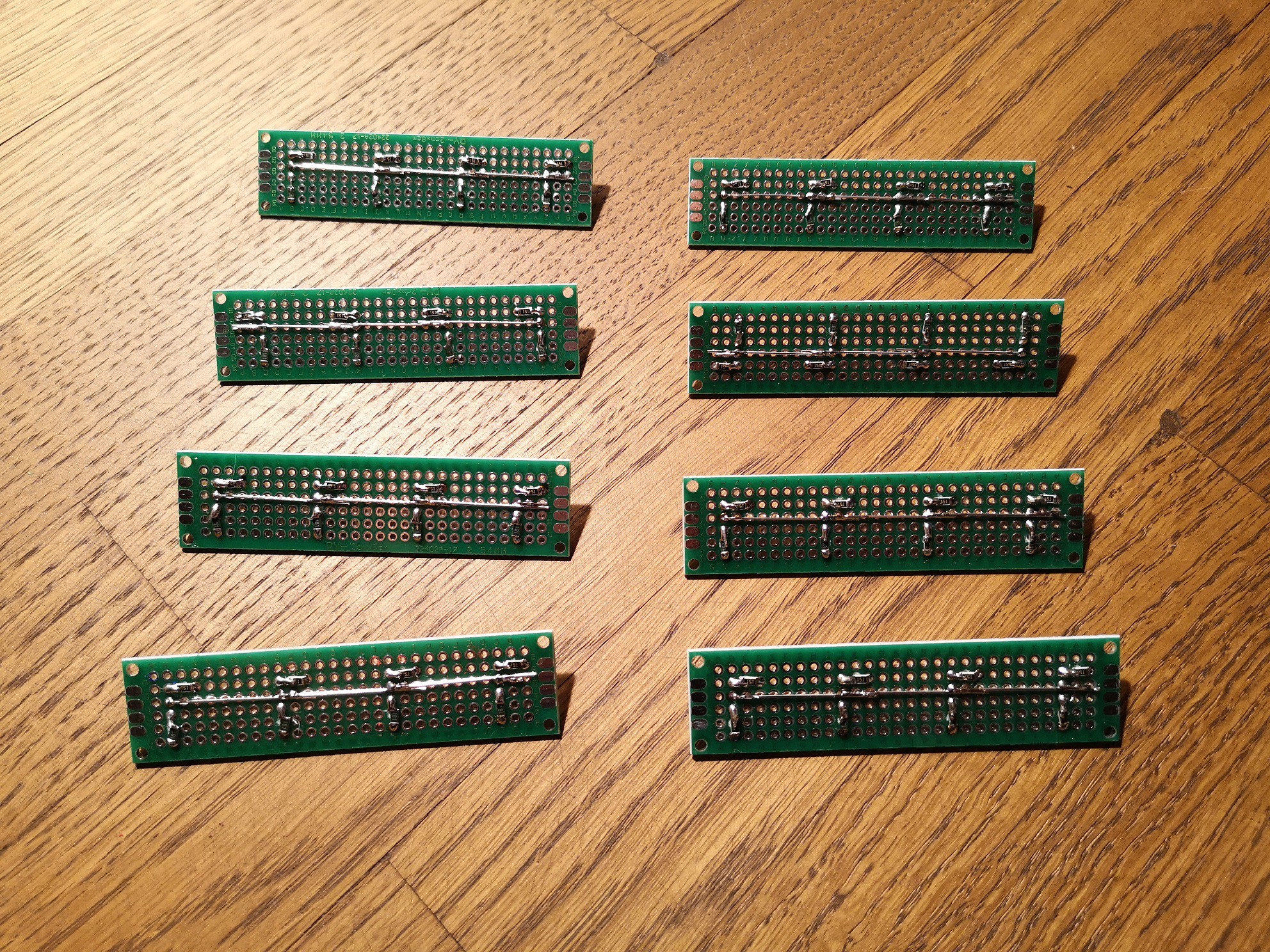
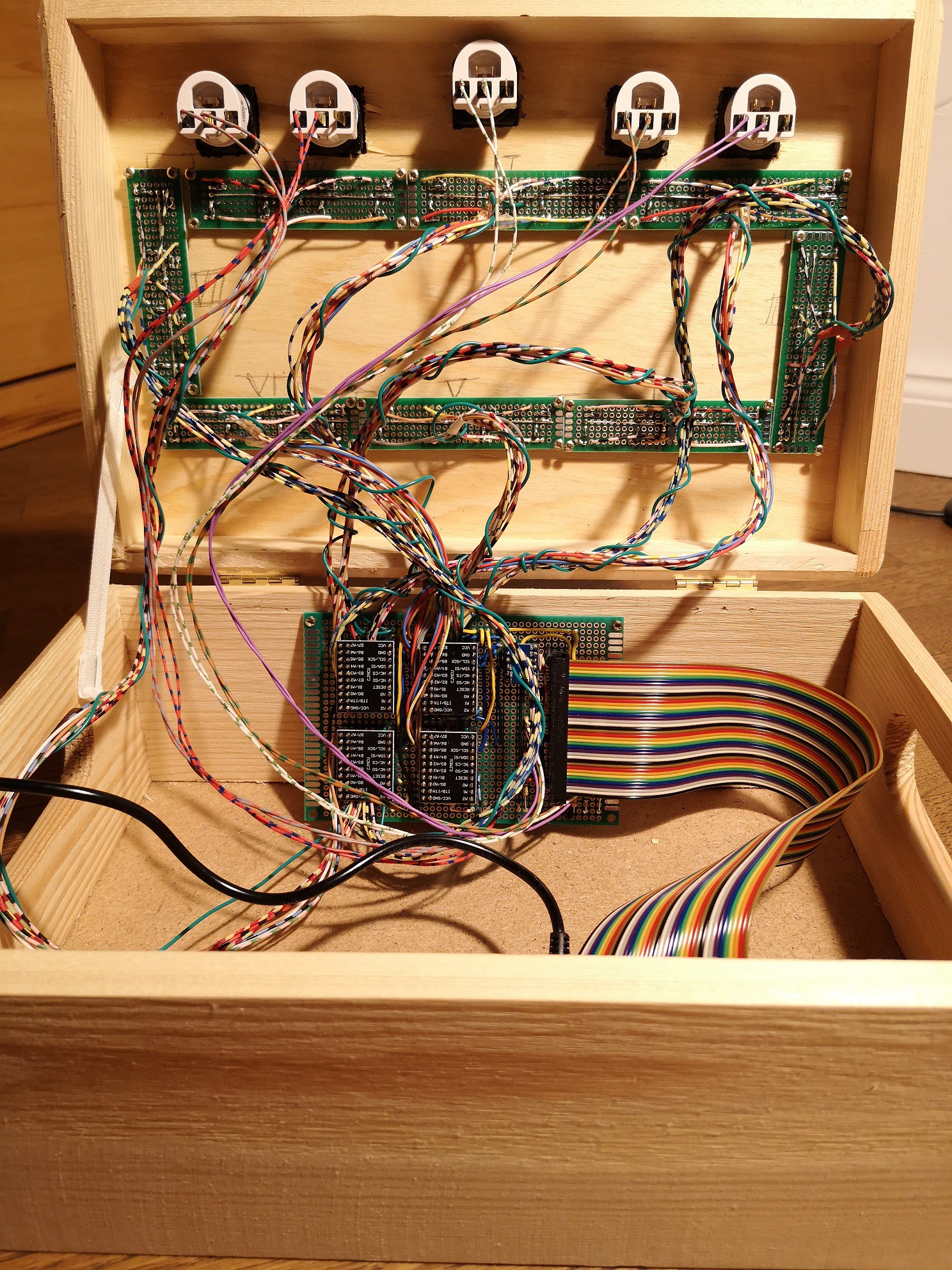
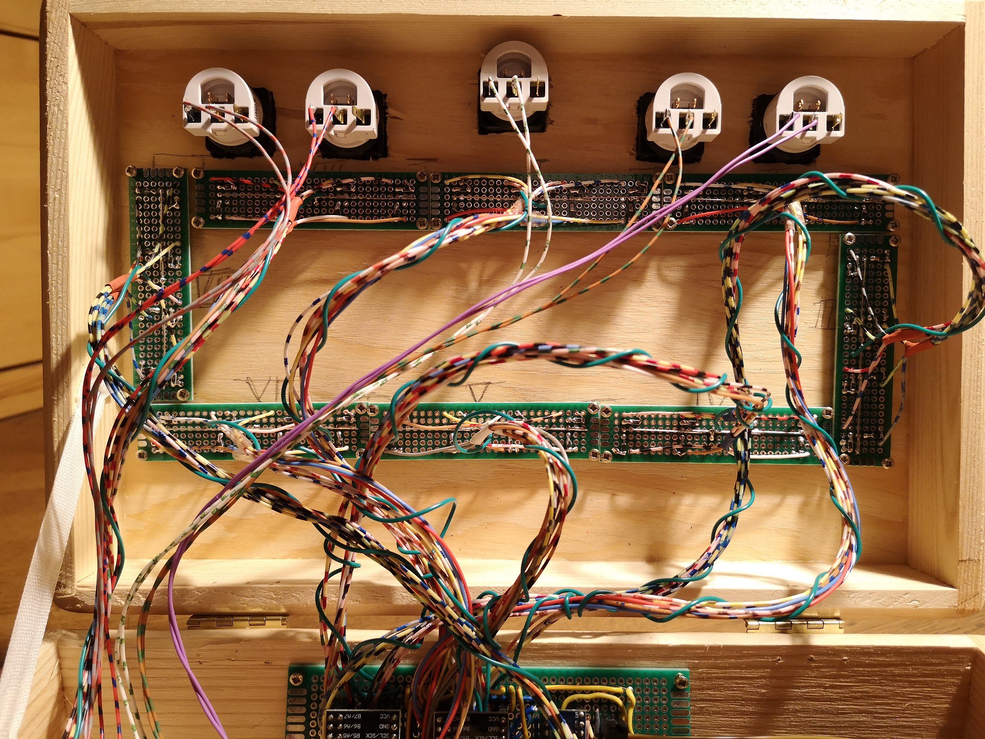
As you can see below in the schematic, the engineering of the hardware part was not a lot. But soldering took some time (see pictures). I was lucky that my stepfather helped me with the manual work. ;) Thanks!


 leo.currie
 Jon durrant
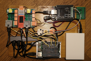
The assembly looks very well done. Like to see this project come to fruition.