 EK
EKA quadrature encoder is an encoder that measures both speed and direction. It's quad (meaning 4) because there's two sensors that can give two values (1 or 0).
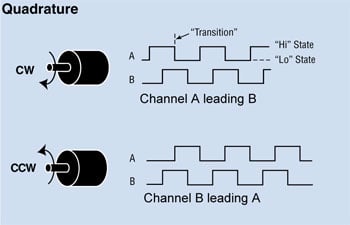
There are two square waveforms that are 90 degrees out of phase with each other. The direction is known depending on the order. The frequency is known depending on how many.
 [source] Also more information available here
It is possible to increase the resolution of the encoder by detecting both the leading and trailing edges of the pulse. When done for both channels, it quadruples the resolution aka pulses per revolution.
Here are the alternative encoder methods, and the reason for choosing magnetic over them:
| Encoder Method | Reason for Not Choosing |
| Optical | End device would be deployed in a dusty environment where optical could be prone to errors |
| Magnet on drive shaft | Backlash in gearbox of the device makes the movement from the drive gear different than the actual on the output gear |
| Field oriented control | Design of this device should be portable to different configurations, whether that's stepper, brushed, brushless, or even no motor |
Downsides to the magnet approach are the cost of the magnets and the size.
Next step for encoder work is determining the hall-effect sensors, magnets, placement of magnets.
Discussions
Become a Hackaday.io Member
Create an account to leave a comment. Already have an account? Log In.