 setCREATE
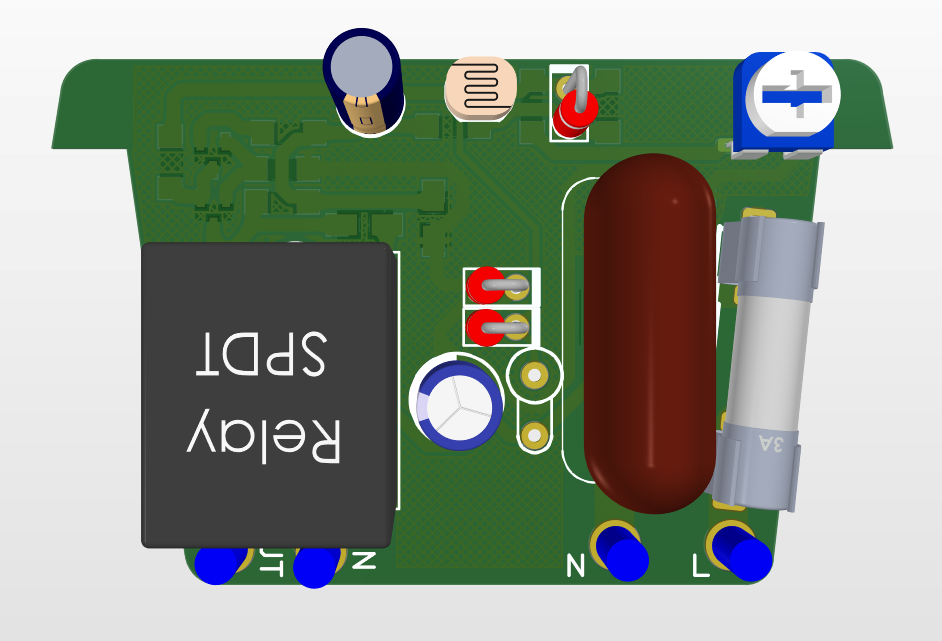
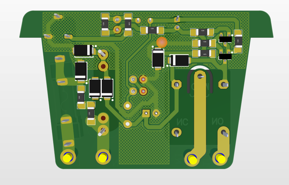
Log no.2: Open Light Switch PCB V1.3
What I've done?
I edited the schematics and redesigned the PCB.
What's New?
- A fuse is added to the circuit
- PCB is designed to be able to mount on the casing
- Power, Input, and output wires are all on the bottom
- PCB is more standard, clearance between tracks is better now (still not perfect)
- PCB is a bit bigger
- It just looks way better, tracks are more organized and no jumper is needed
Where are the files?
You can download the Scheme and the PCB documents in the project files.
What's next?
I will design a casing for the PCB and 3D print it.
Discussions
Become a Hackaday.io Member
Create an account to leave a comment. Already have an account? Log In.