-
Power
12/11/2021 at 23:26 • 0 commentsI've been doing some back of envelope (I don't smoke so no fag packets) with regards to power.
I have three sets of Solar Cells, and I've done some measurements and made some calculations.
Using the SAD lamp as a standard light source for each of the tests.
Small Solar Cell
79 mm x 59 mm
Voltage = 1.59 V
Current = 35 mA
Area = 4661 mm2
Power = 55.6 mW
Power per mm2 = 11.29 uW/mm2
Medium Solar Cell
138 mm x 82 mm
Voltage = 4.64 V
Current = 24 mA
Area = 11316 mm2
Power = 111 mW
Power per mm2 = 9.8 uW/mm2
Large Solar Cell
149 mm x 130 mm
Voltage = 5.19 V
Current = 49.3 mA
Area = 19370 mm2
Power per mm2 = 13.165 uW/mm2
What is interesting is that the Medium Solar Cell is not completely 'active' but the if you just use the 'active' area then the Power per mm2 comes up to 15.41 uW/mm2.
Unfortunately you can't remove the inactive area, so putting a Solar Cell array has to use the lower ratio.
Calculations and Assumptions
Initial idea is to use 6 of the large Solar Cells.
Using the numbers from the previous analysis we have this
6 x 130 mm x 149 mm --> 116220 mm2
This gives 1.53 W @ 5.19 V which gives 294 mA.
This assumes that the light level of the SAD Lamp not going to be the light level in the field.
Let it be 50% this brings it down to --> 147 mA.The Charging of a battery is not going to be 100% efficient.
Let's use 75% which gives 110 mA.
The smallest battery available is 1 AHour.
Using this it would take approx 9 hours to charge the battery.
Short Day
The shortest day is approx 7 hours long.
Having four 1.1 Ah batteries for longevity and power for Torque.
To charge the batteries @ 110mA would take 40 Hours.
This is would be too short even if it's a bright sunny day for the 7 hours on the Shortest Day.
As there are only 7 hours in which to charge the batteries it has to charge 6 times as fast.
Assuming the same technology we have to have
6 x 6 cells --> 36 Solar Cells.
Physically this gives
6 x 130 mm -> 780 mm
6 x 149 mm -> 894 mm
Effectively it is a 1m by 1 m.
This would be physically unstable and also would need a large sheet of Perspex.
Will need to work on the 18 V but this can be solved.
Once I have this I can look at the batteries again.
-
Charging Test
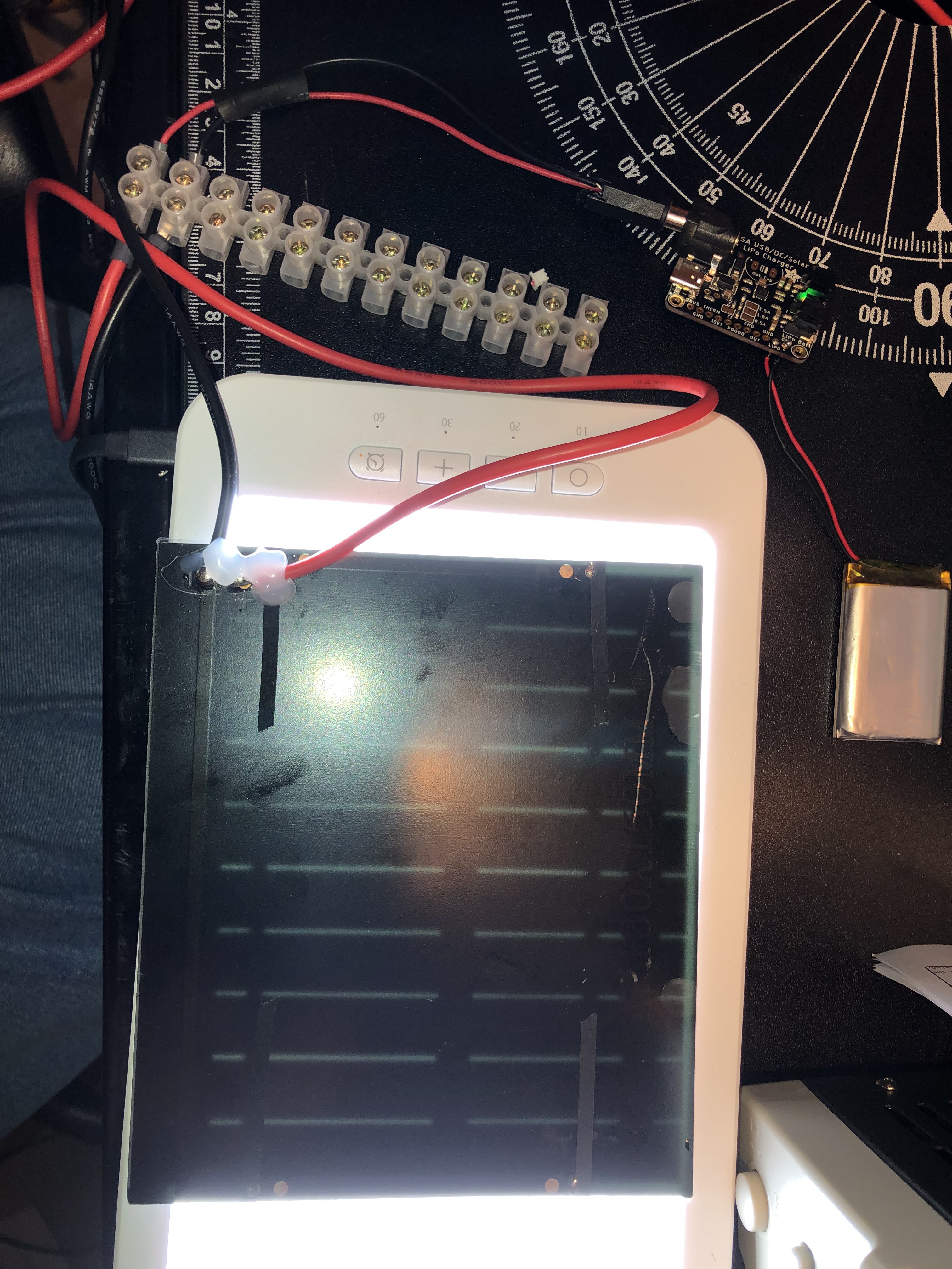
12/03/2021 at 18:05 • 0 commentsThis is a test to see how long using a SAD lamp set to full will take to charge a 1100mA battery.
Last time I made a measurement of the current output when pointing at the sun I got 60 mA. What we get here we will have to see !
![]()
-
Prototype Motion
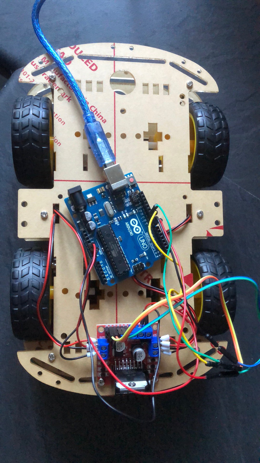
12/01/2021 at 13:03 • 0 commentsThis is the first test on the prototype. The Arduino is programmed to go forward, rotate left, then rotate right and then finally go backwards.
What did I discover ?
Well the first thing was that the Motor Driver didn't want to operate when the power was connected to the 5V pin. Swapped over to using the 12 V pin and the stand off test succeeded !
Next the same test with the Arduino connected to a battery pack. Again stood off this worked fine.
Next test has it all sat on the floor.
The rover couldn't move forward with the battery pack on it.
Holding the pack above it started to move with the right hand side dragging a bit. No rotation.
I think that the Arduino itself can't provide a stiff enough supply while the Motors are under load.
I think the plan for a separate supply will need to be given, USB 2 only provides 2 Amps, so I need to get a bit more than that but let's see.
![]()
-
Power
11/26/2021 at 13:04 • 0 commentsI've now taken 6 PV sheets and soldered wires to them.
Using this I was able to rig up a simple motor to them. I then took them out into the sun and the motor started to turn, faster than I was expecting it to do so.
I've ordered some charger boards and some lipo batteries.Next will be to see if I can get the stepper motor to work with them.
-
Yet it Moves
11/23/2021 at 22:27 • 0 commentsI have been able to get a stepper motor to rotate and have understood controlling it's revolutions.
Note all voltages are DC.
There is a Stepper Motor Driver, this is rated at 9v to 42v. It doesn't do anything if you feed it less than 9v.
The stepper motor I have is rated at 3.6v bit on doing some reading around this can be taken higher.
Using the sig gen to generate a 5v square wave initially I could adjust the frequency thus the speed. Also I was able to change the Duty Cycle quite significantly.
The maximum frequency was approx 19.5 kHz. I didn't note the current consumption but it was approx 200 mA at 11 v. No idea about the torque level but this is quite a pleasing outcome. I will see if I ramp the frequency using the sig gen and see if it 'sings' as I expect it to.This does start to put thoughts about power of the Rover. Will need at least 10v but may want to have something higher for 'traction' but stick to 5v/3.3v for the electronics.
Also as one of the areas to explore will be to mount some Photo Voltaics to recharge some batteries I will need to consider this carefully.

