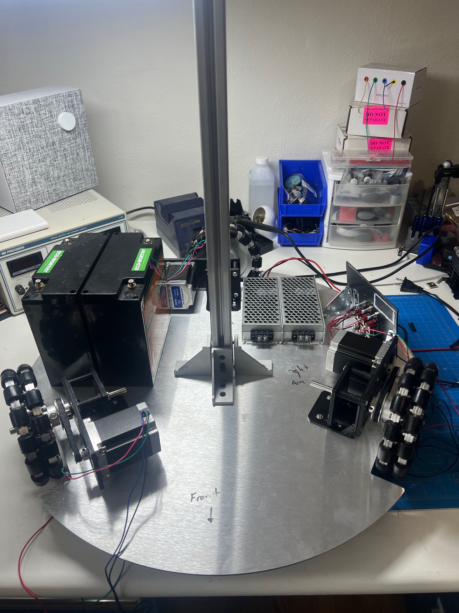
Lots was done today! I mounted the drive units and mocked up the placement of the DC-DC convertors, batteries and power panel. I had to mark the base front left right as my mind was being fried trying to remember. Then I compared it to the CAD model to ensure that there would not be clearance issues with anything.
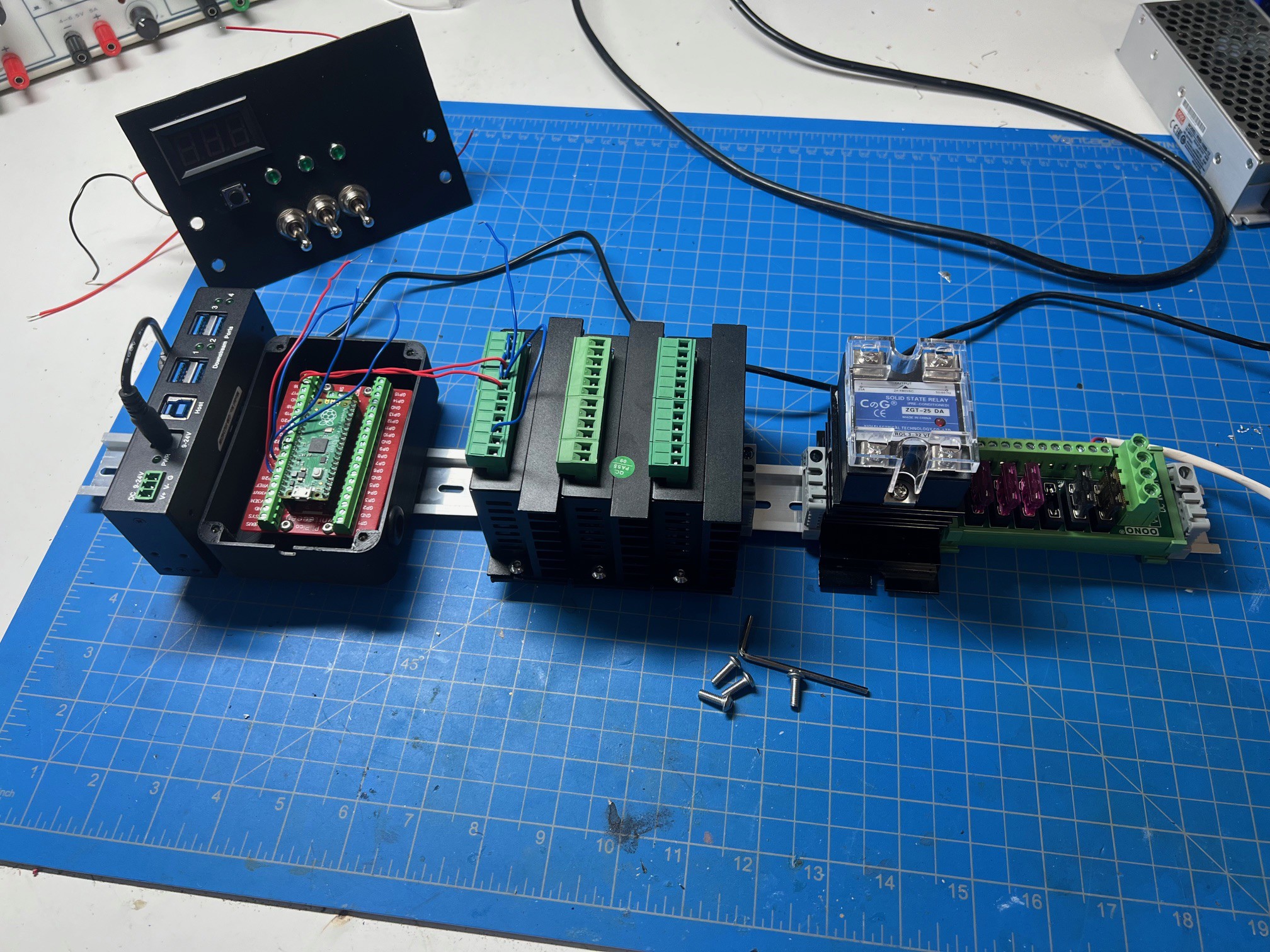
I tightened down the motor drive units. The 3D printed parts will work for testing, but I will need to swap to machined aluminum to ensure the G2 belts stay tight. New longer DIN rail came in and I mounted the 12volt fuse distribution unit, motor power solid state relay, the 3 motor drivers, Pico and the USB 3.0 hub. (Yay COTS parts!)
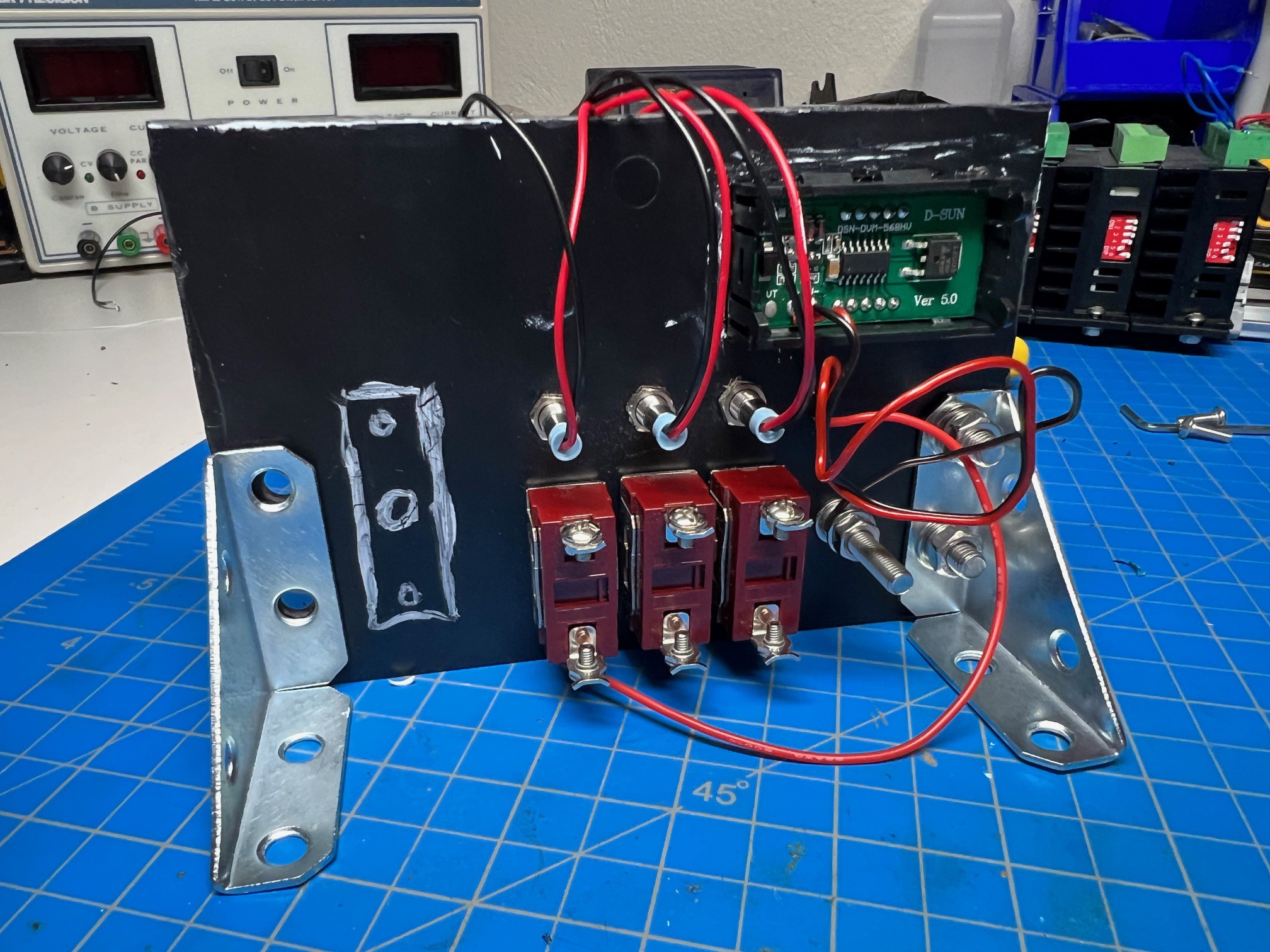
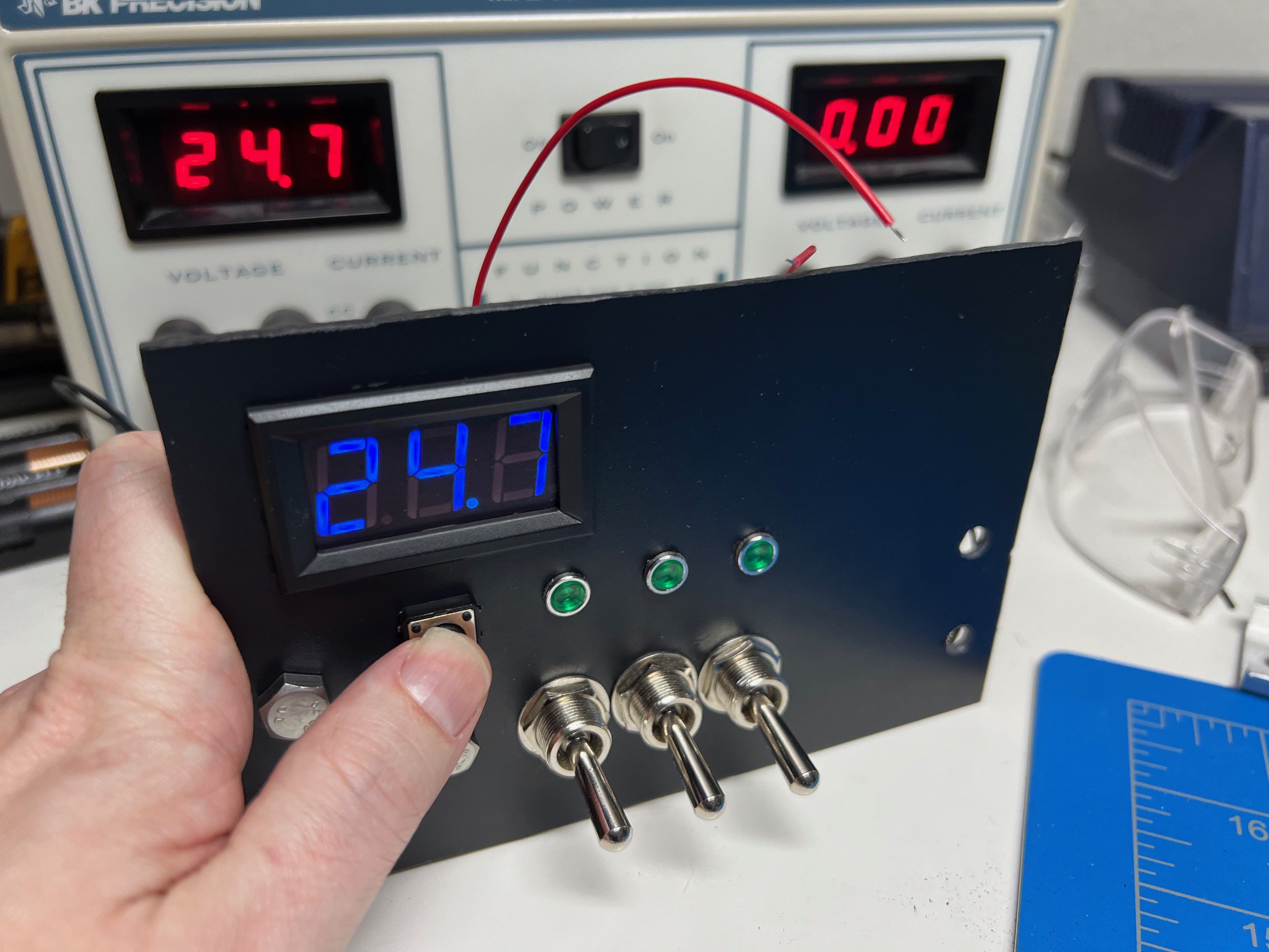
I also did quite a lot of building on the power panel also. It has a momentary push button voltage meter, this will be for main battery voltage. I also added a star negative bolt as the switches will be doing positive side. The negative/bolt will just pass though.
Also found out something pretty cool when the motors are connected to the stepper drivers and the drivers have not power applied (like when the solid state relay is off) You can back drive the motors, so you can push the robot around or out of your way if it is not in a move state. Fancy!


 Apollo Timbers
Discussions
Become a Hackaday.io Member
Create an account to leave a comment. Already have an account? Log In.