Close
0%
0%

Cheapest Possible Motorized Laser Z-Axis Table

Ultra simple Z-axis table design, good enough for focus automation for different materials.

Similar projects worth following
I set out to design the cheapest, most integrated, and automated Z-Axis table that would still be good enough to run reasonably complex jobs without the need to manually adjust anything - except maybe once at the beginning of a complex job - but it's optional.

Since, I don't know, 2016 or so, I have a K40 laser. I had great fun with it and learned an infinite amount about CO2 laser engraving, cutting, and got a glimpse into whatever else one can do with a laser.

The K40, at the price it comes at, needs some rather mandatory upgrades right out of the box but I won't go into those here.

I want to concentrate on the Z-Axis, or the laser engraving platform your material rests on while it's being cut.

Shortly after I got the machine, I removed the god-awful original cutting table and replaced it with a simple construction that would just hold the work in place. I didn't want to spend the $200 on the LightObject Z-Axis Table because I didn't know how much I would end up using the thing. It looks great though!

I, instead, suffered through pretty much every issue in the book of cutting until I learned enough to know where the focus point of the laser needs to be and how to get it there. However, with my first table setup that simply wasn't possible so I designed a really crappy, held together by gravity, Z-axis table that allowed me to manually adjust all four corners but not more.

Years later, when I really needed to adjust the table to engrave something tall, it escalated quickly....

  • Assembly

    Timo Birnschein12/01/2021 at 15:53 3 comments

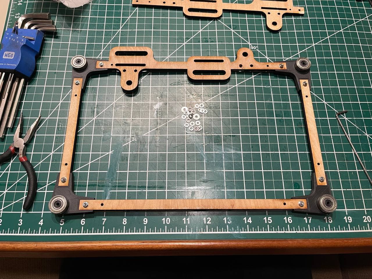
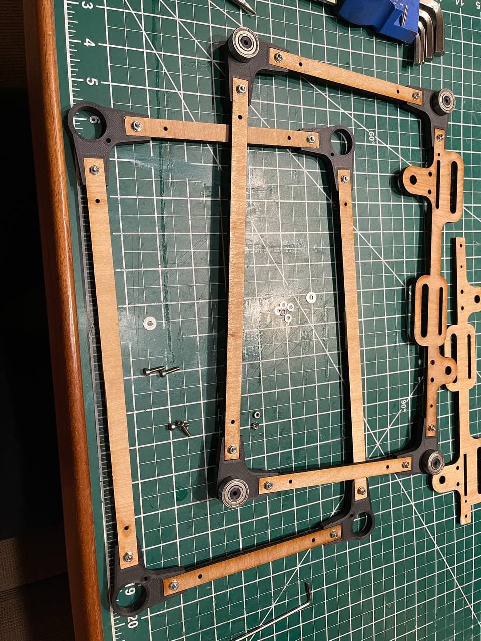
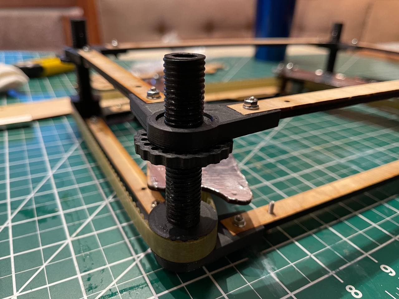
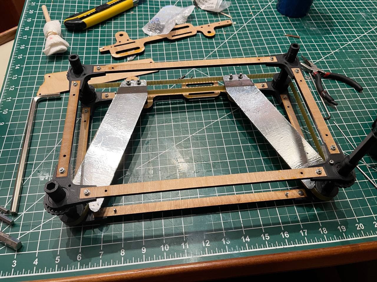
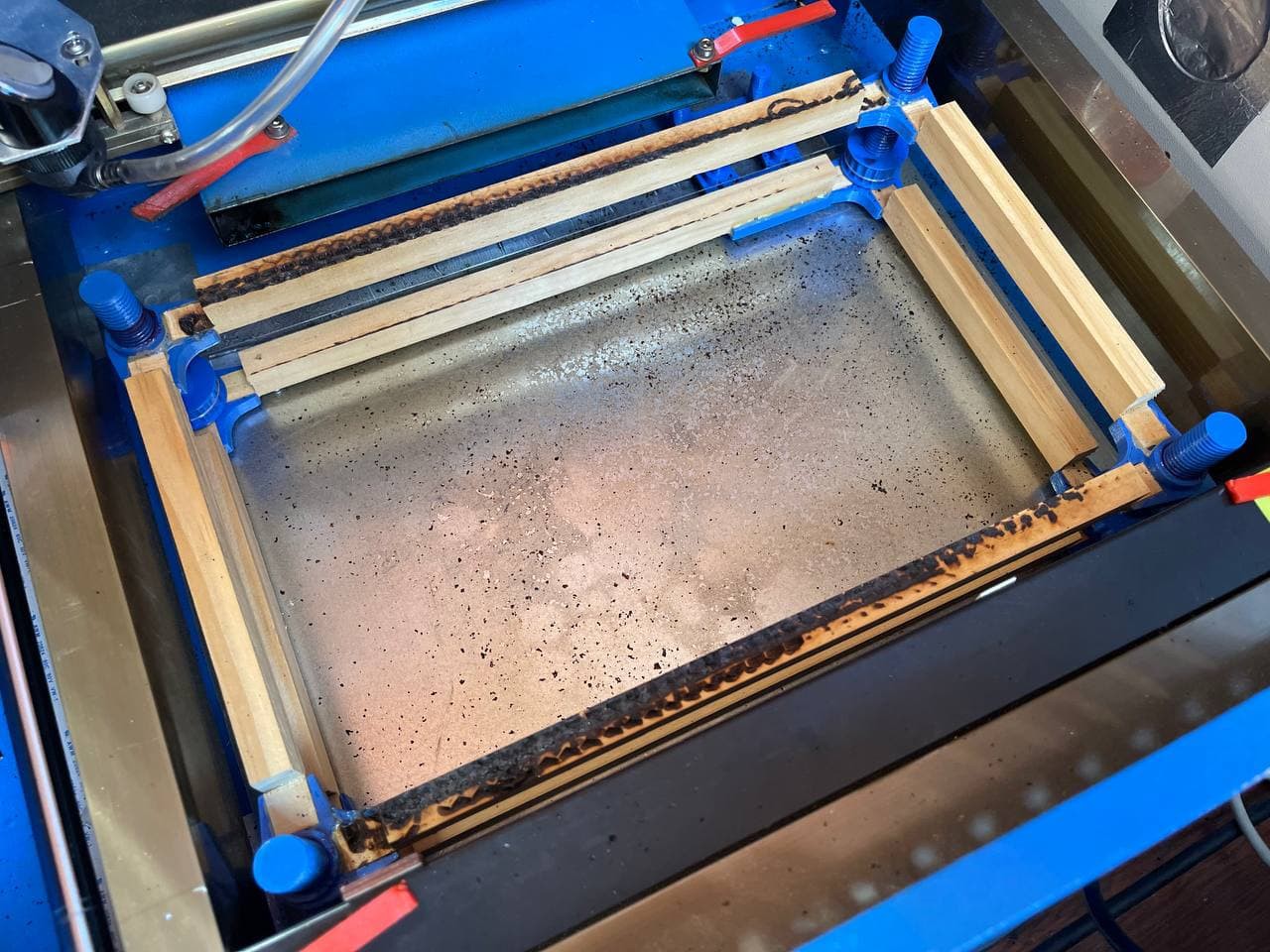
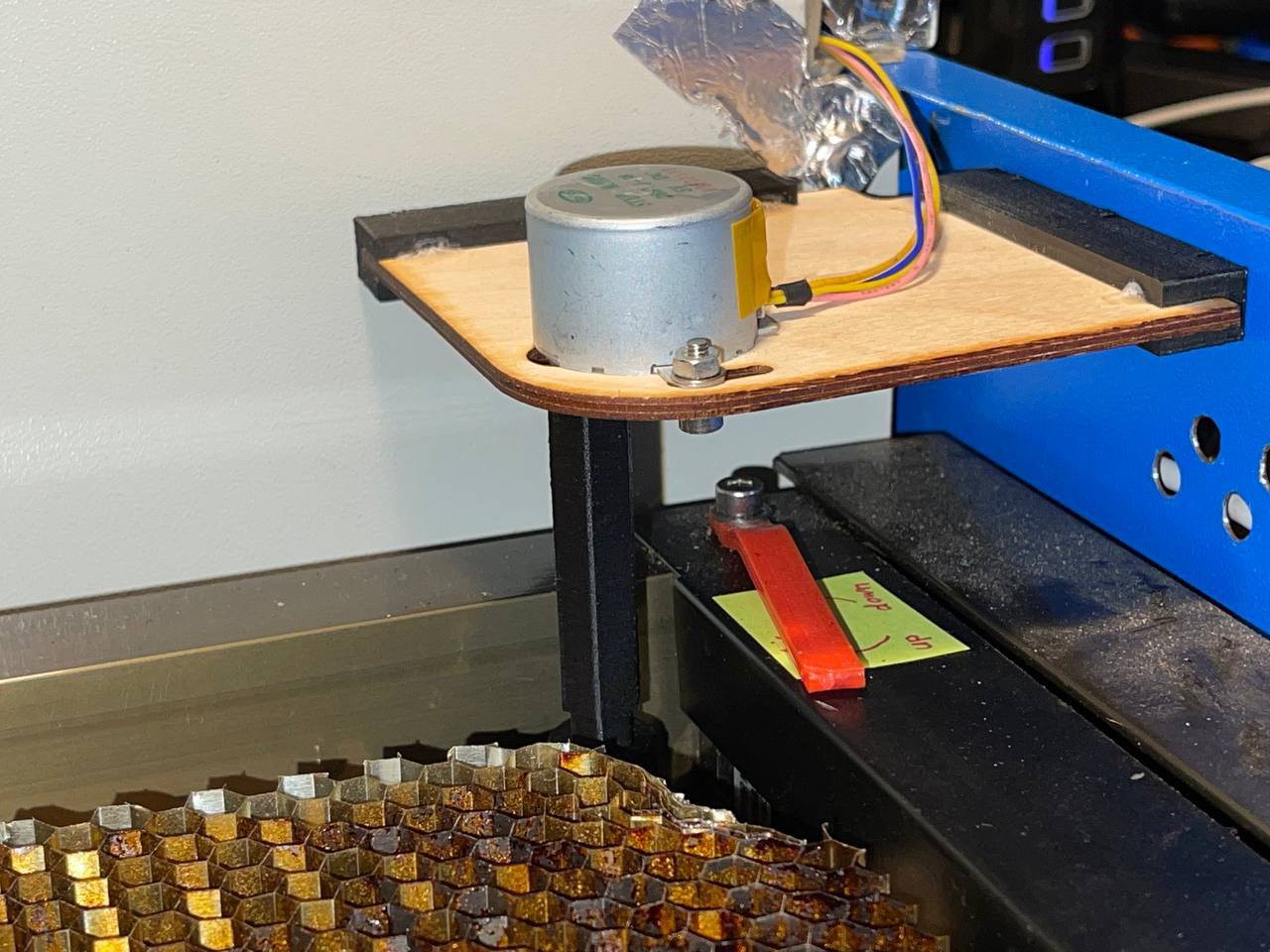
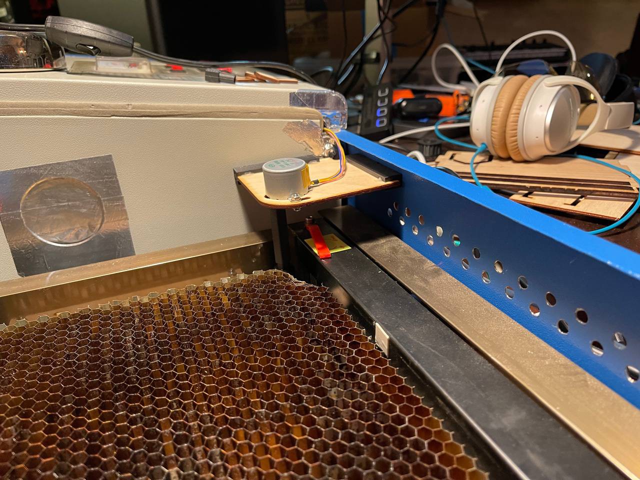
    Just some pictures from putting this thing together as it's pretty straight forward.

    Added some grease! 

    The belt is way too thick and bending it alone causes so much friction in this design. I will attempt to redesign this to work with a short GT2 belt that can be easily purchased in the US. That will make this design more opensource compatible. Stay tuned.
  • Getting the Focus Right - Every Time

    Timo Birnschein12/01/2021 at 15:50 0 comments

    I installed a geared stepper motor connected to one of the spindles via a 3D printed hex adapter directly to the stepper motor shaft. These motors are about $3 which is really a good deal for what they can do - as long as you don't care about axial play.

    The motor is mounted to a sheet of plywood and "mounted" to a corner of the laser compartment using nothing but 6 small magnets. That allows me to remove the motor with ease if needed.

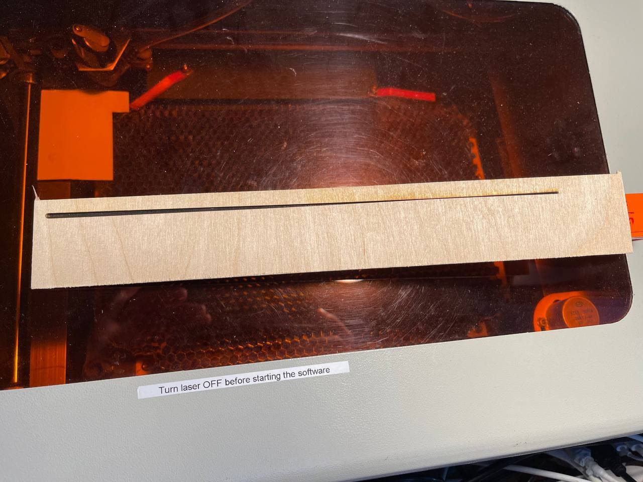
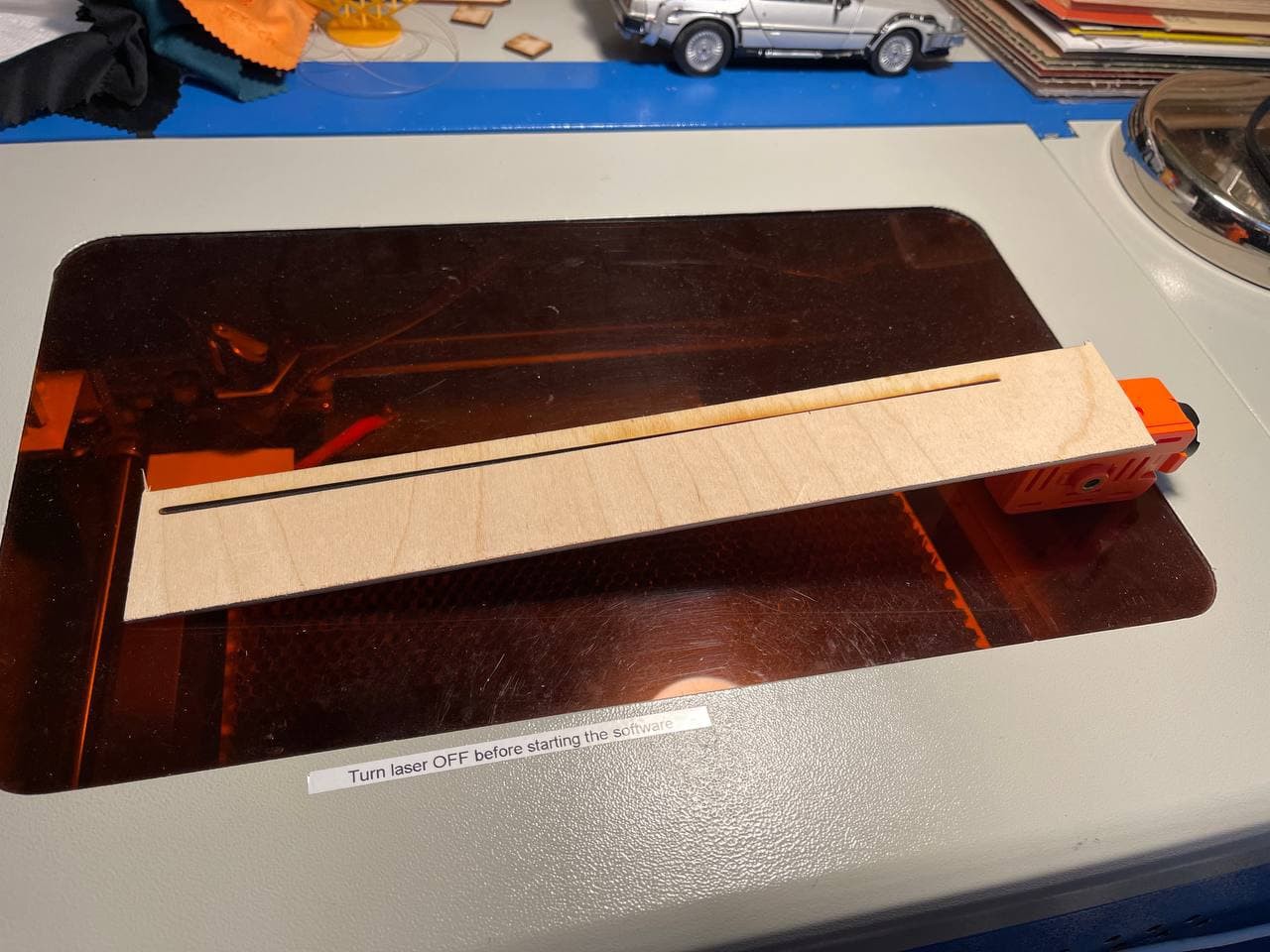
    To get the focus setup properly this time, and after leveling the table against the laser head at all four corners, I drove the table down as far as I could (about 25mm travel is available) and added a piece of wood at an angle.

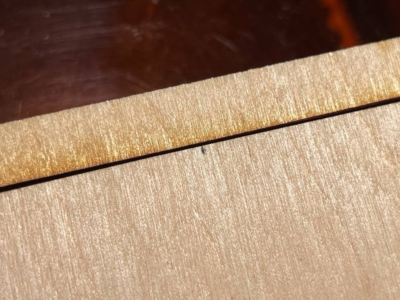
    Then I'd sweep a 100% power laser line from left to right to get the full focus range engraved.

    Then, I took a very close look at the engraved line and mark the spot that appears most in focus without touching the part! NOT touching it is really important because I needed to know the distance between the laser head and that position in Z. 

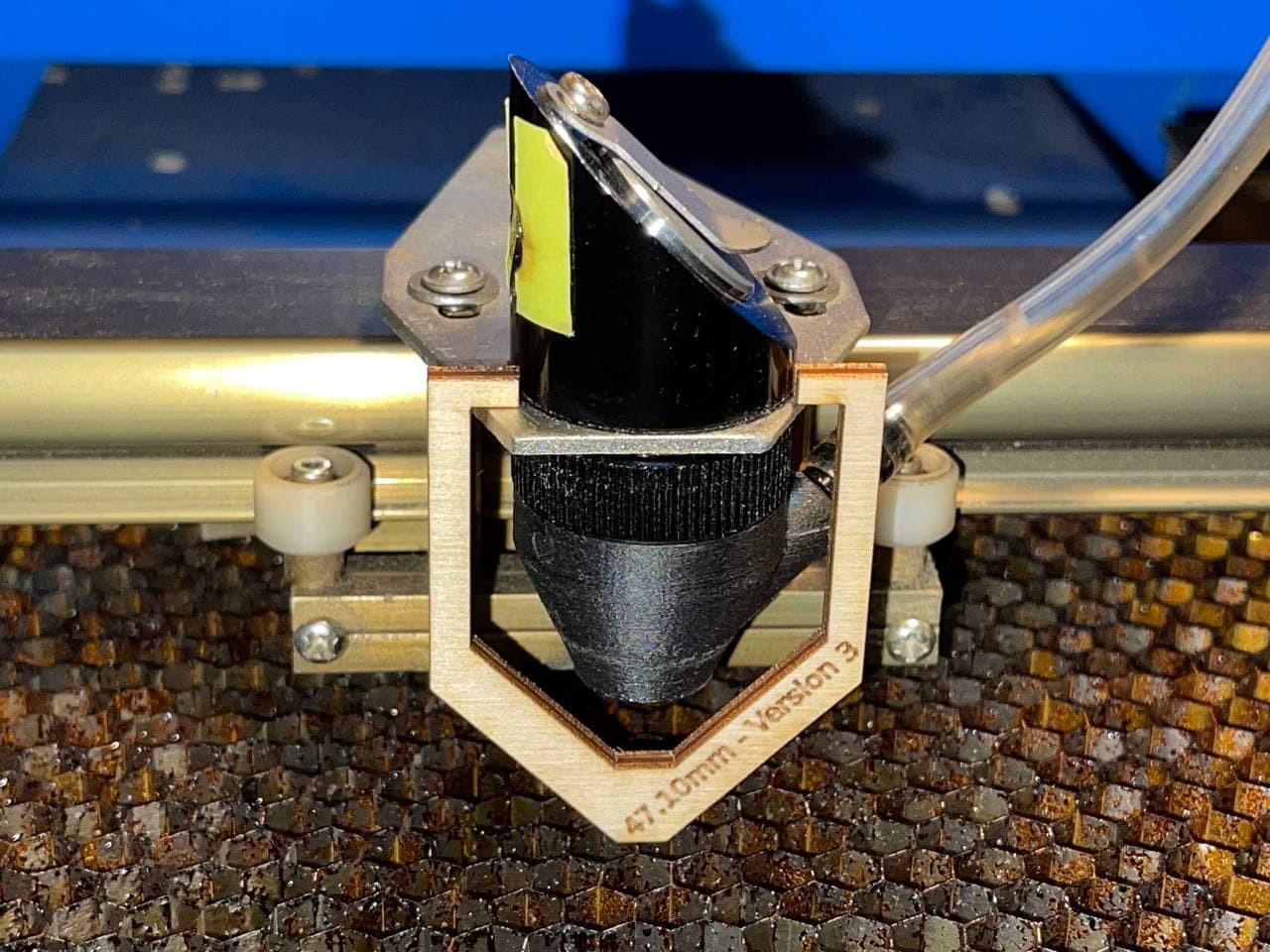
    I took my calipers out and gently extended it to get the distance between the top piece of the laser head (where the mirror is mounted) and the dot I made with a sharpy. In my case that's 47.10 mm. I used that value to design a simple hanging template that I can now use to adjust my laser focus with to be EXACTLY on the surface of the work-piece.

    All I need to do now is drive the table down, drive it back up to get rid of the slop and play and gently 0.1mm by 0.1mm move it further until the dangling focus temple stops swinging in the exhaust fan air flow. Perfection! From this point forward, this laser is pretty much twice as efficient since I finally have a good way to setup the focus and actually get to the correct material depth every single time!

    In fact I was able to cut 3mm and 5mm plywood TWICE as fast producing much less charred results with finer details.

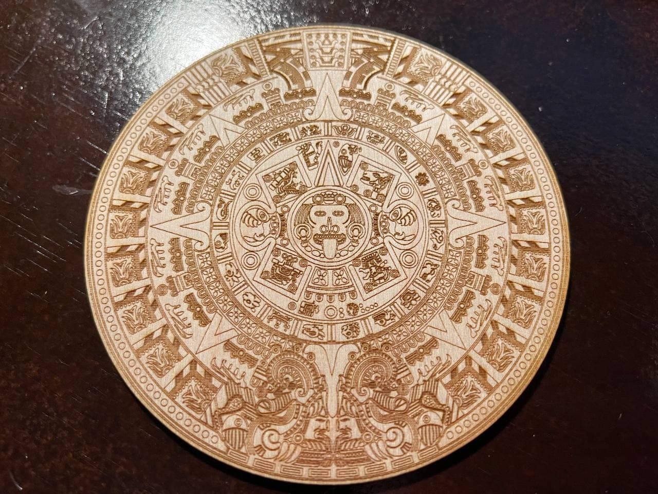
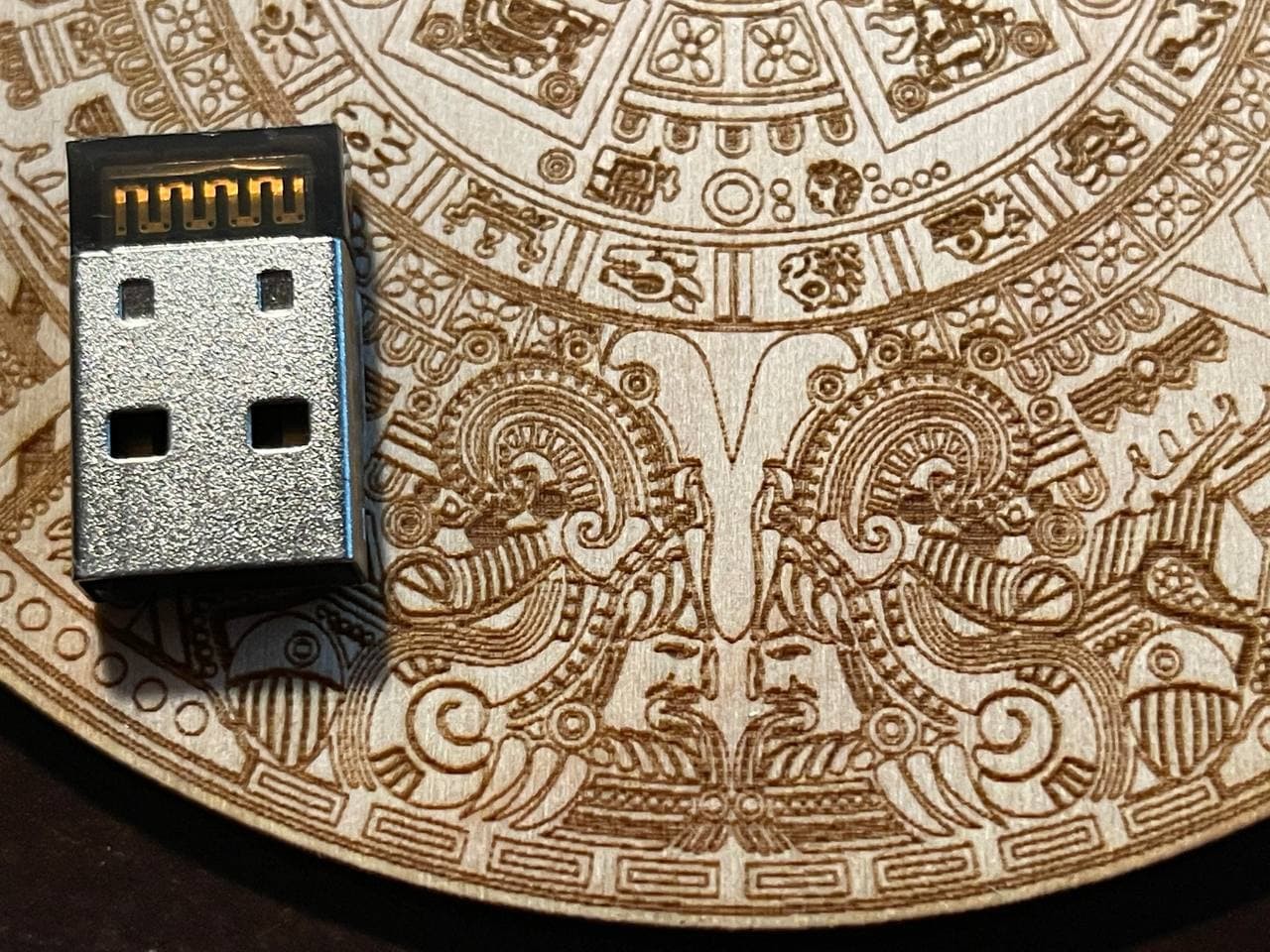
    Speaking of details... I engraved this Aztec calendar yesterday. This job takes about one hour of engraving on this setup at 300dpi (mostly limited by how fast my GRBL controller can ingest gCode for individual raster pixels). I am super impressed with this result and look forward to more lazing! with LAZERS!

    (Always wear your safety gear!)

  • That Escalated Quickly! The New Guy...

    Timo Birnschein12/01/2021 at 15:37 0 comments

    With this experience shattering the timeline of my actual project, I went into Solidworks and looked at my old design. After years of CAD work, I learned a thing or two and I immediately realized my pretty heavy oversights on the first design. In my defense, I designed this in a day and put it together the next.

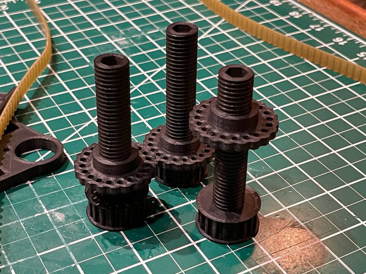
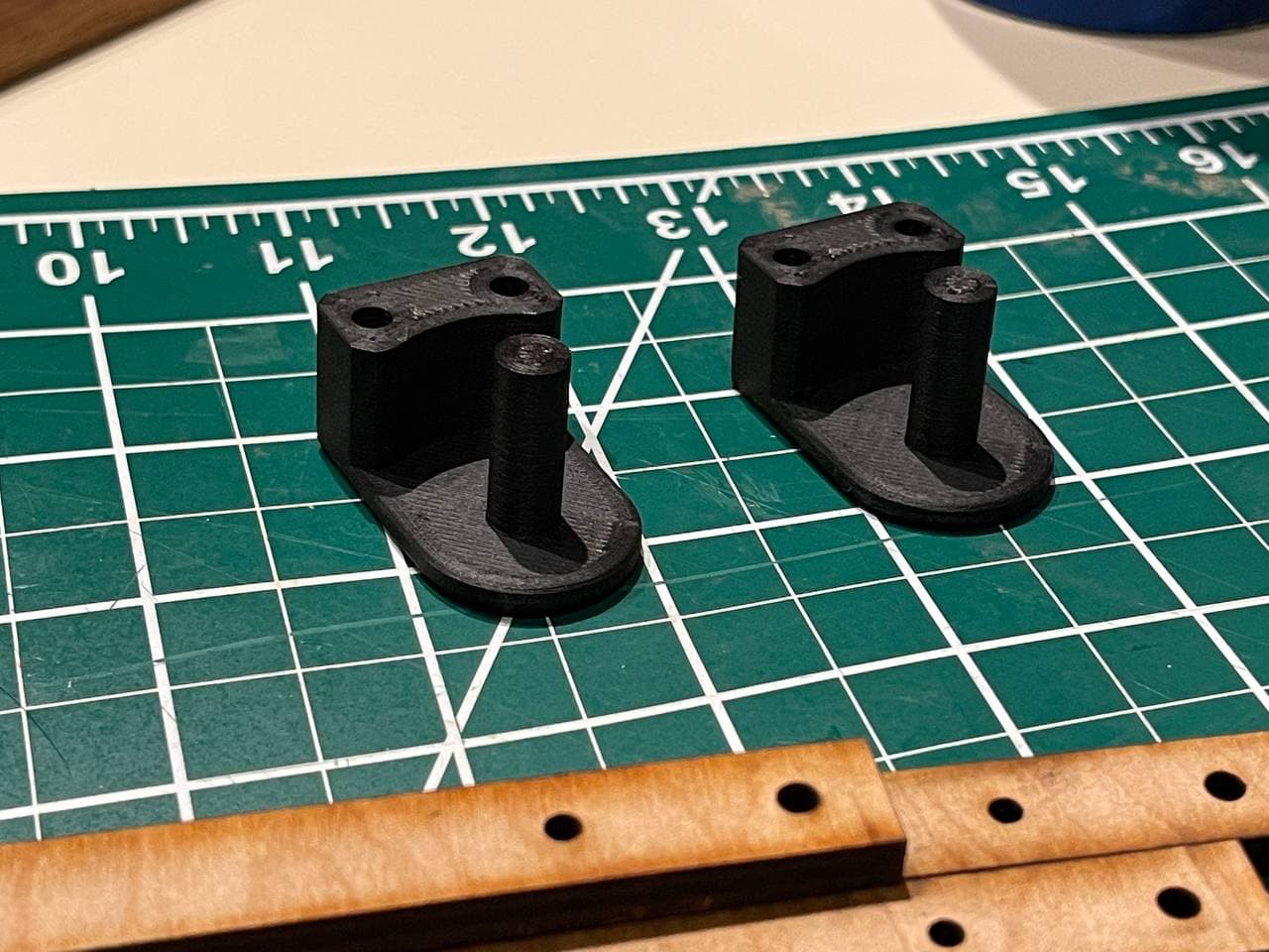
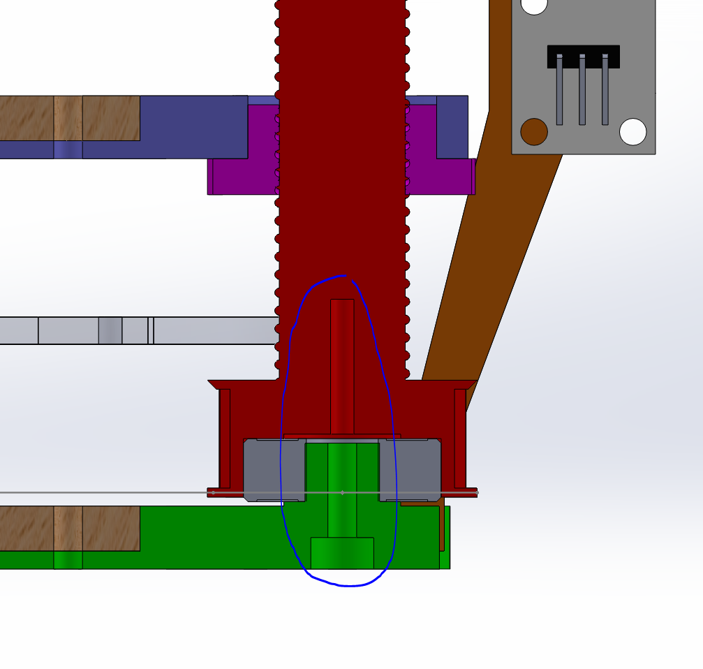
    First of all, the spindles were not held by anything. They just has a ball bearing pushed into them from the bottom and shaft of the ball bearing sat on a 3D printed pin. Nothing was stopping it from coming apart. So the first major upgrade was a M3 screw that just holds the spindle down.

    It doesn't need to be tight, it's just there, to keep it from falling out. Remember, this table really only needs to hold grams and has no lateral loads to bare whatsoever!

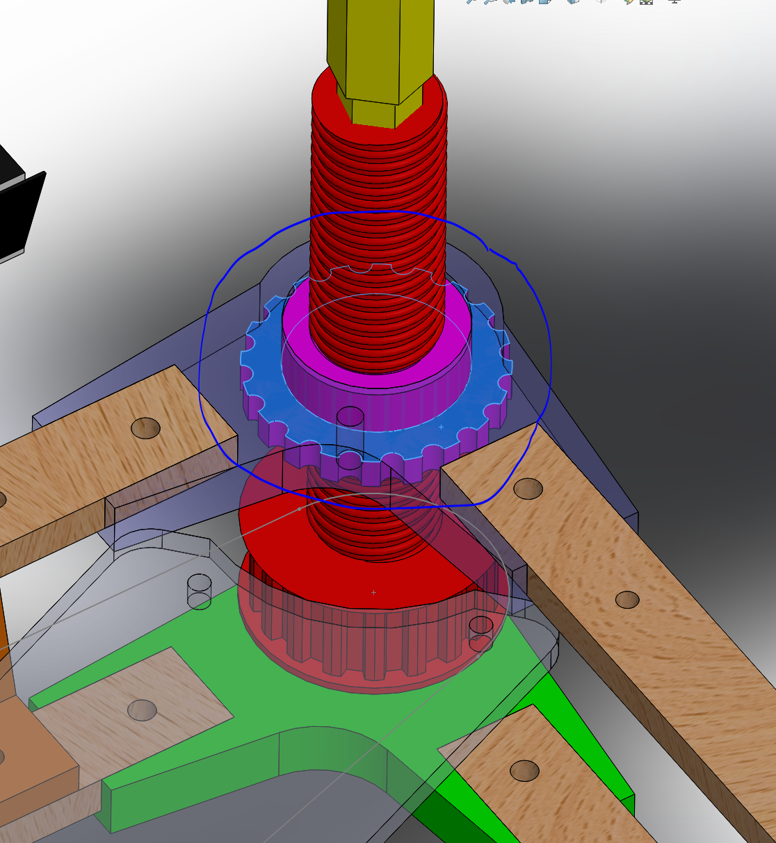
    The second major upgrade was adding additional spindle nuts to the design such that I could adjust the table's four corners just by rotating these a little bit. 

    These nuts are then locked in place simply by adding another M3 screw to the hole in the transparent blue corner module. I cannot stress enough how much easier it is to adjust the height of each corner now. This construction is also just held down by gravity but since I have parts on the table and the honeycomb, too, it's working thus far.

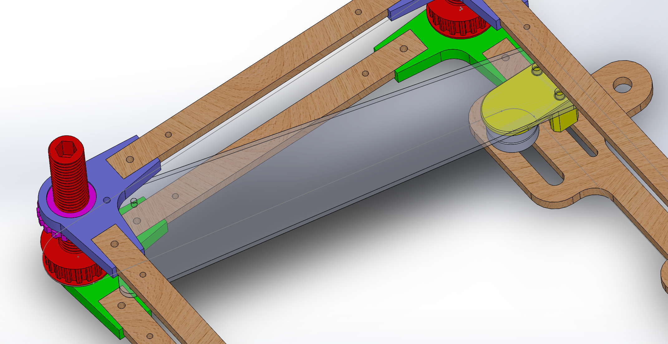
    The next bit was to make the table work with my 1440mm belt. TOTALLY the wrong belt for the job, but I had it sitting around and didn't have any other use for it. So it was either throw it away or use it in this contraption (with the massive friction it comes with).

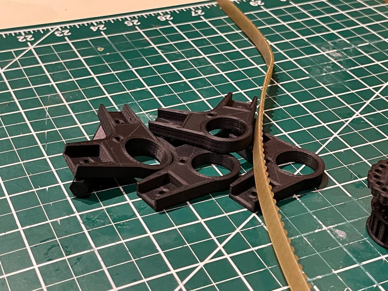
    To do that, I added adjustable idler bearings to the opposite side of the table. Yes, the belt goes all the way across. Again, I had it, I knew it is too long for this.

    But since that's pretty exposed, I needed to add a shield over the belt to protect it from being burned by the laser during job execution. I did that on both idler bearings and also added a piece of aluminum tape to make the wood immune to laser light.

    One last thing I indented to add is an endstop switch to be able to properly calibrate the laser focus automatically each time the thing fires up. There are two problems with that: First, the laser is easy to adjust manually once you have Z-Axis control and a template to get the focus right, and second the mechanical switch I have lying around has too much force to allow me to drive the "gravity held together table" against it from the top by moving the table downwards reliably. Mounting the switch above the table and driving the table up is still... well, on the table, but for now, this works great.

  • What's wrong with you?

    Timo Birnschein12/01/2021 at 15:20 0 comments

    This is that table. The design already has all the properties of what I wanted to accomplish here: It's either 3D printed or laser cut parts, all components are integrated into simple multi-purpose parts that are easy to print by pretty much anyone, and it can be belt driven.

    I made a huge error during my initial design, though, and calculated the belt length completely wrong (I had one 1440mm long T5 belt sitting on the shelve for years) and couldn't get the belt drive to work. So I used fishing wire to wrap around the printed T5 pulleys and kinda sorta used it that way to manually adjust the thing.

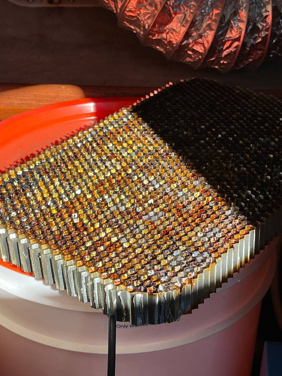
    On top of the frame sits a honycomb mesh which is worth every penny!

    As one can see, it's well used!

    The table was usable until I got the great idea to finally add a stepper motor to it. I designed a hex-piece that fits over one of the threaded rods and allows me to connect my stepper motor.

    After I connected it to my controller board (which I wisely designed to eventually maybe support this feature) I drove the table up and down few times only to realize that my "held together by gravity and wood-glue" setup is about to entirely disintegrate. That was five minutes after I tested the stepper for the first time. Great win!

    Well, I guess I knew that wood glue doesn't work with PLA but at the time of putting the first table together, I was desperate and just needed this thing to be complete. It lasted many years of not being moved but when I moved it, every single joint broke and the ball-bearings just popped out of their seats. Great job. Well done.

View all 4 project logs

Enjoy this project?

Share

Discussions

Similar Projects

Does this project spark your interest?

Become a member to follow this project and never miss any updates