 Tim
TimTesting more detailed gates will be easier in spice. First step is to replicate the inverter. Testcircuit shown below.
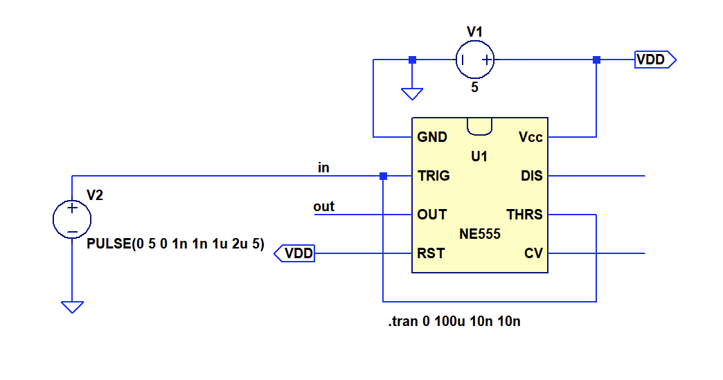
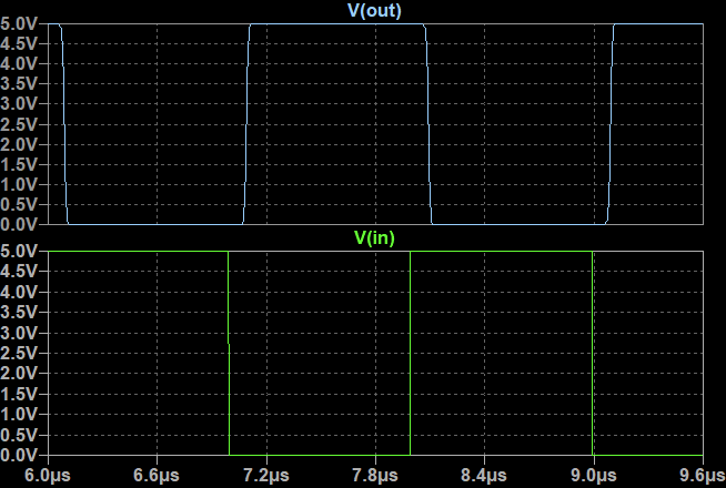
The first attempt with the model that comes with LTSpice showed correction operation of the circuit (plot below), however the timing was significantly faster than the real measurements.
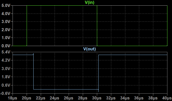
I switched to a model for CMOS version of the NE555, the TLC555, that was provided by TI. I found a modified version for LTSpice on the net. The timing looks much more simular to the real device now, although the CMOS version still seems to be about 3x faster than the original bipolar version.
Now on to building and testing some gates
Inverter Implementation
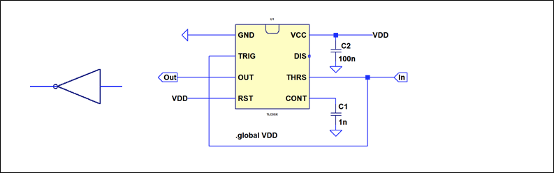
Self explanatory and tested before
NAND2 Implementation
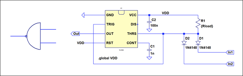
Here we are adding a wired AND at the input of the schmitt-trigger inverter formed by the NE555.
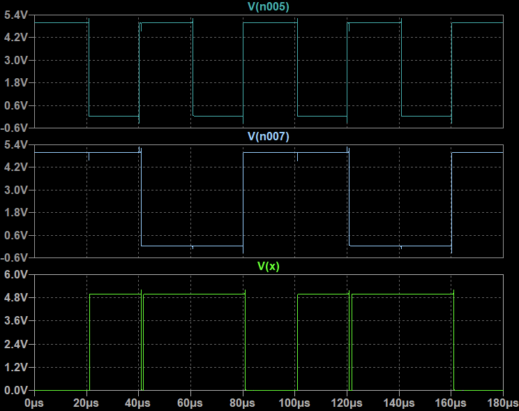
The gate works nicely, but it's obvios that the very high propagation delay of the NE555 inverters used at the input of the NAND2 lead to some glitches.
NOR2 implementaion
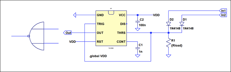
Turns out a NOR2 gate can also be implemented easily. Since the NE555 has a push-pull output we can use a wired OR at the input of the gate.
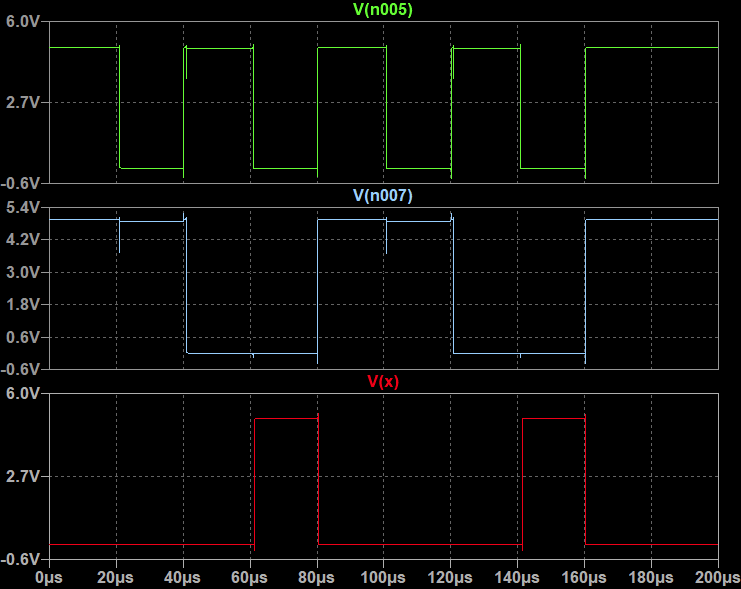
Works nicely
Edit: Turns out the NOR gate implementation is somewhat marginal. While the NE555 has a push-pull output driver, it uses darlington NPN for the pull up. This means it cannot pull up to VCC/VDD. An additional diode in the current path, like in the wired-OR, drops too much voltage for the NOR gate to work reliabilty.
Conclusions
We now got a basic library of NOT, NOR2, NAND2 that can be easily explanded to wider input gates. All combinatoric gates can be formed from set of gates. Next step: Latches
Discussions
Become a Hackaday.io Member
Create an account to leave a comment. Already have an account? Log In.