 Tim
TimIt's nice to simulate individual gates, but better the check whether they work together as well. I created a spice library describing the individual gates the I simultated in LTSpice before. The description of the NAND gate and Latch can be seen below:
.SUBCKT ne_NAND2 A B Y
XU1 N001 N002 N001 VCC Y NC_01 VCC 0 TLC55X
C1 N002 0 1n
C2 VCC 0 100n
R1 VCC N001 {RL}
D1 N001 A RTL_DIODE
D2 N001 B RTL_DIODE
.ENDS ne_NAND2

.SUBCKT ne_LATCH E D QN
XU1 N001 N002 N001 VCC QN NC_01 VCC 0 TLC55X
C1 N002 0 1n
C2 VCC 0 100n
R1 N001 0 {RL}
Q1 D P001 N001 0 RTL_NPN
R2 VCC N001 {RL}
R3 E P001 {RL}
.ENDS DLATCH
Simulating the synthesized design turned out to be quite an ordeal. The TLC555 spice model makes extensive use of parametrised switches. This are described differently in different versions of spice, specifically LTSpice and NGSpice. I found adoption of the TLC555 spice model to both NGSpice and LTspice. Somehow I did not manage to get the full counter design to simulate properly with NGspice due to problems with the operating point analyises.
After many fruitless attempts I exported the entire netlist to LTSpice where it now resides in a testbench.
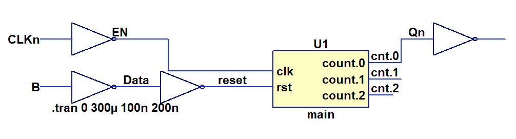 Eventually I managed to simulate the counter and was able to show that it actually works:
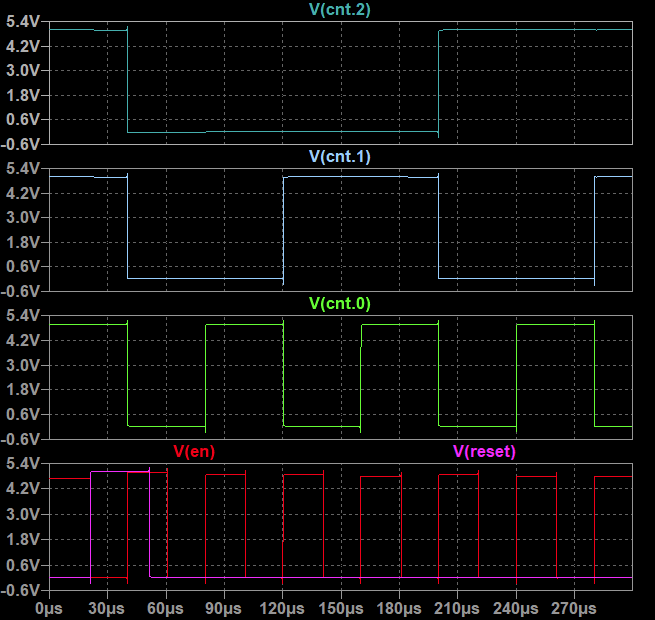
What I learned along the way: For some inexplicable reason the NOR gate implementation with wired-OR does not work if it is used within the full circuit. I was not able to identify the root cause, but solved it by excluding this gate type for now. Simulation is unfortunately taking forever due to convergence issues - Spice does not really like switches.
Nevertheless - design proven, now on to the cell library.
Discussions
Become a Hackaday.io Member
Create an account to leave a comment. Already have an account? Log In.