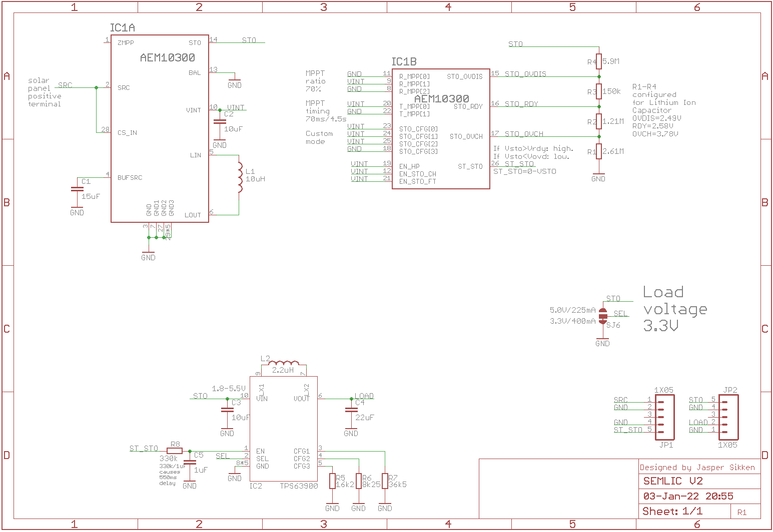
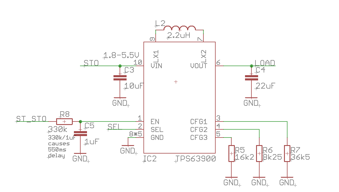
The previous version, SEMLIC V1, has a linear voltage regulator to create a 2.2V/150mA supply for an application. This low voltage was chosen because the Lithium Ion Capacitor usable voltage range is 2.5-3.8V and the linear regulator needs 0.3V head room to regulate well. Since many wireless development boards work on 3.3V I wanted to design this new board. SEMLIC V2 uses a TPS63900 buck boost converter which can deliver 3.3V/400mA from the Lithium Ion Capacitor and it has an awesome 75nA quiescent current. I think the E-peas' new AEM10300, Lithium Ion Capacitors and the new TPS63900 is an awesome new combination for batteryfree IoT applications.

I use AEM10300 storage status pin ST_STO to enable the buck boost converter.


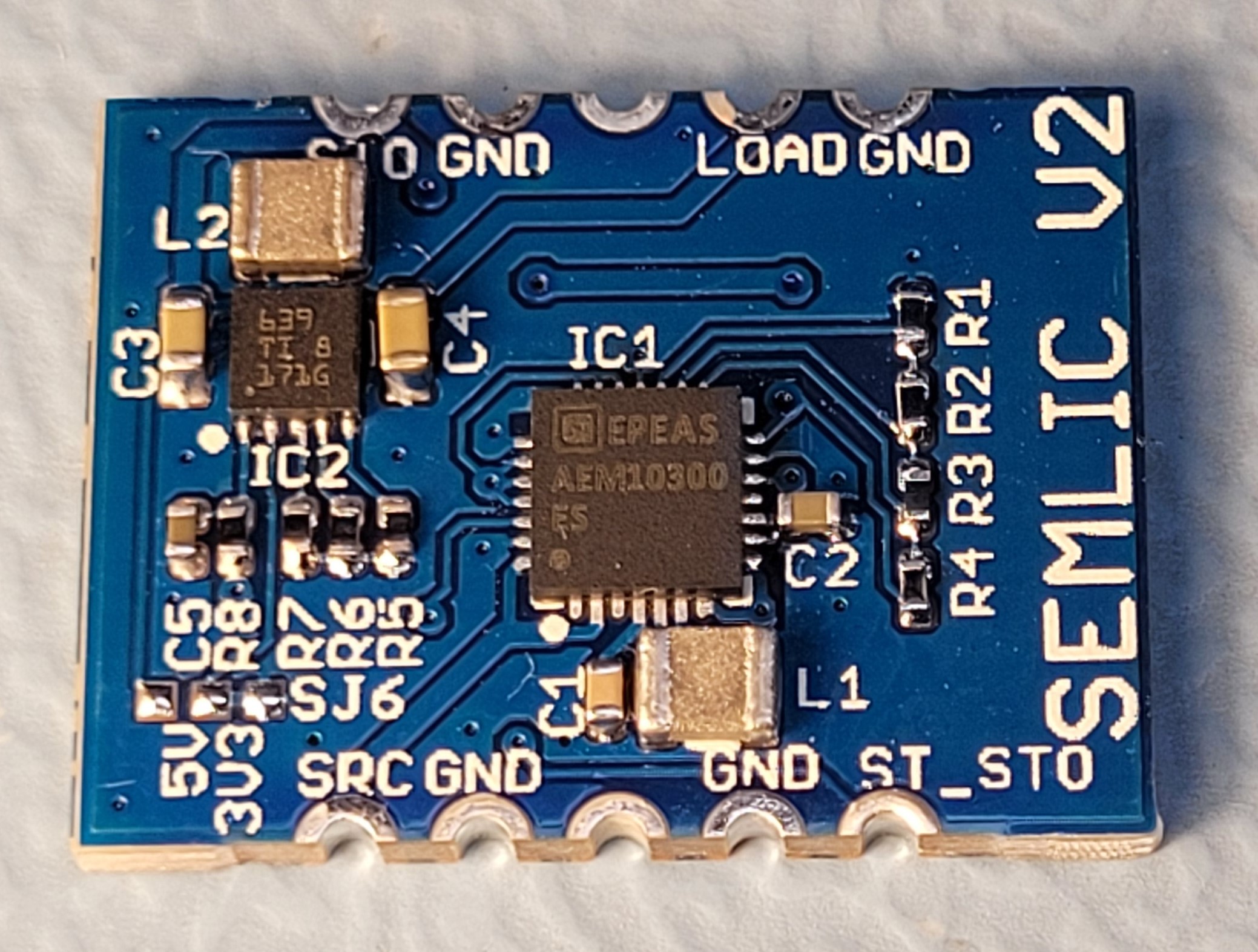
During current chip shortage I was able to buy 220pcs TPS63900 from ICsoso. I have assembled one PCB myself and it looks like this.

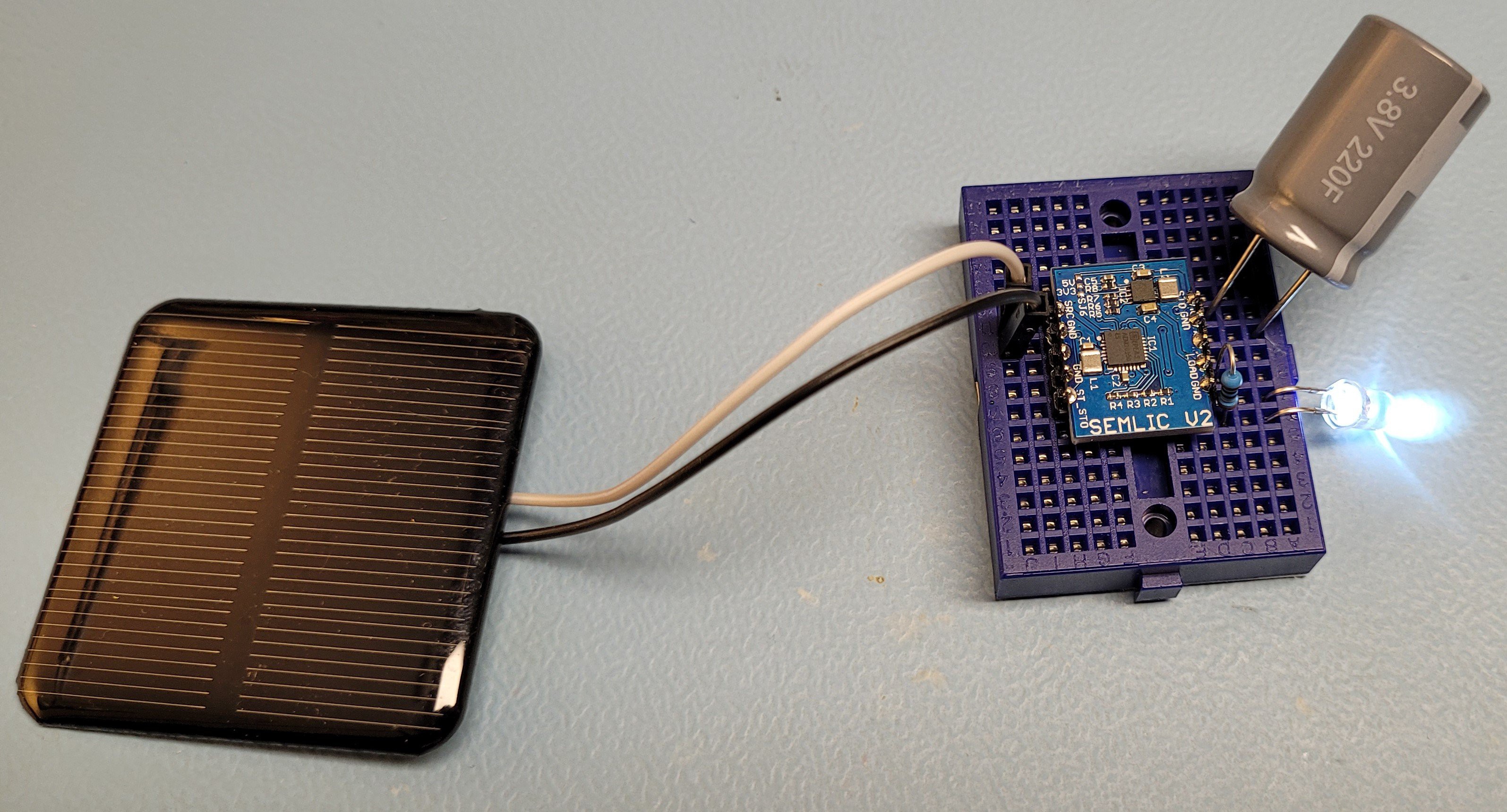
And this is how it looks when connected to a 220F 3.8F lithium Ion Capacitor

I have performed functional testing and everything worked except the AEM10300 ST_STO storage status pin. It should be high when the storage voltage is higher than a set theshold, but I noticed it goes down from time to time, even with high enough storage voltage, and it depends on the amount of light on the solar panel. I believe I have read the AEM10300 datasheet well, the function of ST_STO is clearly described. First I thought it was a solder issue and so I have tested with the older SEMLIC V1 board (with LDO) and it has the same ST_STO behavior. I know AEM10300 is an engineering sample, and a few months ago I also found an error in the AEM10330 datasheet, so I should not expect too much. I contacted E-peas for support. They replyed "The AEM10300 is a battery charger: its internal circuitry is no longer supplied when energy on the source is too small to keep it alive. Thus the status pins drops". So I was sad the ST_STO pin function is incorrectly described in the DS_AEM10300_Rev1.0 datasheet, that my board is not working as expected, and that I have wasted few evenings debugging. Lesson learned: For new chips, especially engineering samples, don't assume the datasheet is correct.
OK now quickly design a new board to solve the problem
 Jasper Sikken
Discussions
Become a Hackaday.io Member
Create an account to leave a comment. Already have an account? Log In.
I'm currently attempting a project using the AEM10300 and stumbled across this, what error did you find in the AEM10300 datasheet that you mention here?
Are you sure? yes | no