To have confidence in a test circuit, it is useful for the test circuit to test itself :-) This mode:
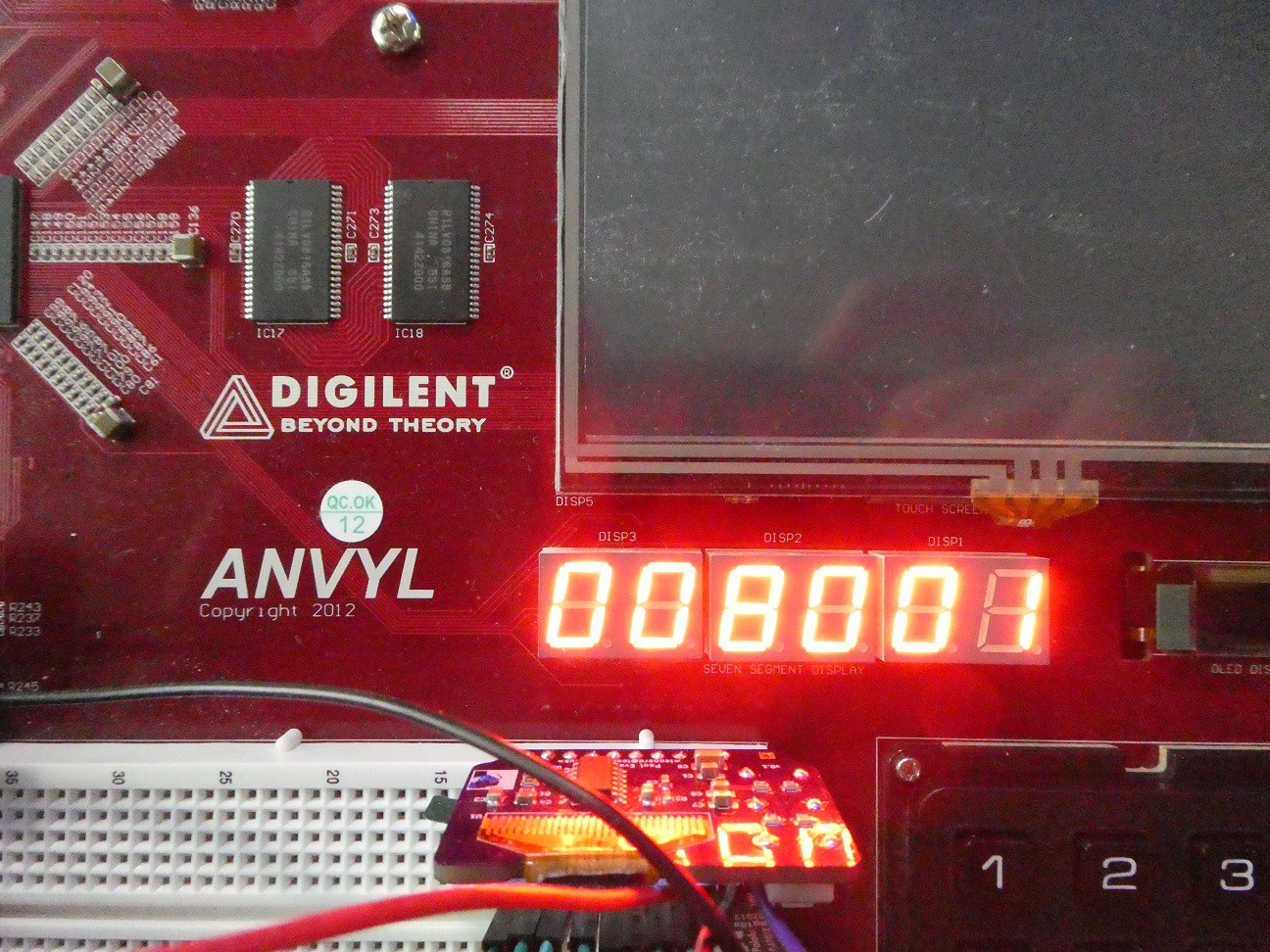
- Displays the UART mode in somewhat cryptic way in 6-digit 7-seg LED
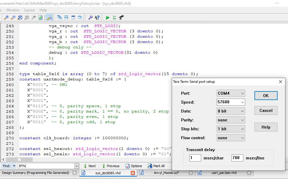
UART is two separate circuits (SER2PAR and PAR2SER) that I reuse in many projects. They support a variety of 8-bit per character transmit and receive frames. The terminal program on the host should be set to same setting (8-N-1 in this case)
Anvyl board switches 2..0 select the mode as visible in the image below.


(note 700ms delay per line - this is to allow time for the trace of HEX2MEM microcode to display before processing next incoming character, more about this below)
- Echos the characters coming from UART input (RX) back to output and also to TTY2VGA. This allows testing those components too.
To simplify top level object, the TTY, video RAM, chargen RAM and VGA controller are wrapped up in one component called TTY2VGA:
- VGA mode: 640*480, 25MHz pixel clock
- Text mode: 80*60 characters, 8*8 pixels
- Video RAM: 4k, dual port. The port connected to TTY controller is read/write (read is used when scroll-up is needed, this is of course a bad design as a top-row register pointer could allow using write on that side) and the port connected to VGA controller is read only. Both ports take x, y (row/col) and internally a hardware "multiplication" is done to find out the character code address (A = Y*MAXCOL+X)
- Character generator ROM: 128 characters (0-127 ASCII, 128-255 are simply inverted in the circuit), total of 1k
- Hardware cursor in two modes (underscore and block)
- Color is hard-coded but could easily be extended by addition of 4k color RAM, similar to video RAM
 zpekic
Discussions
Become a Hackaday.io Member
Create an account to leave a comment. Already have an account? Log In.