 zpekic
With the memory and I/O map looking good (see test approach in previous log), I decided to complete both MiniMax85 single board computers, expecting they would work.
Well, they didn't :-(
After exhausting all the usual simple debugging steps (voltages and frequencies as expected on the right pins, testing ICs outside as much as possible (e.g. the EEPROMs), or changing ICs - I have 2 of each major chips) I still could not find the reason why the SBC was completely unresponsive on the serial port.
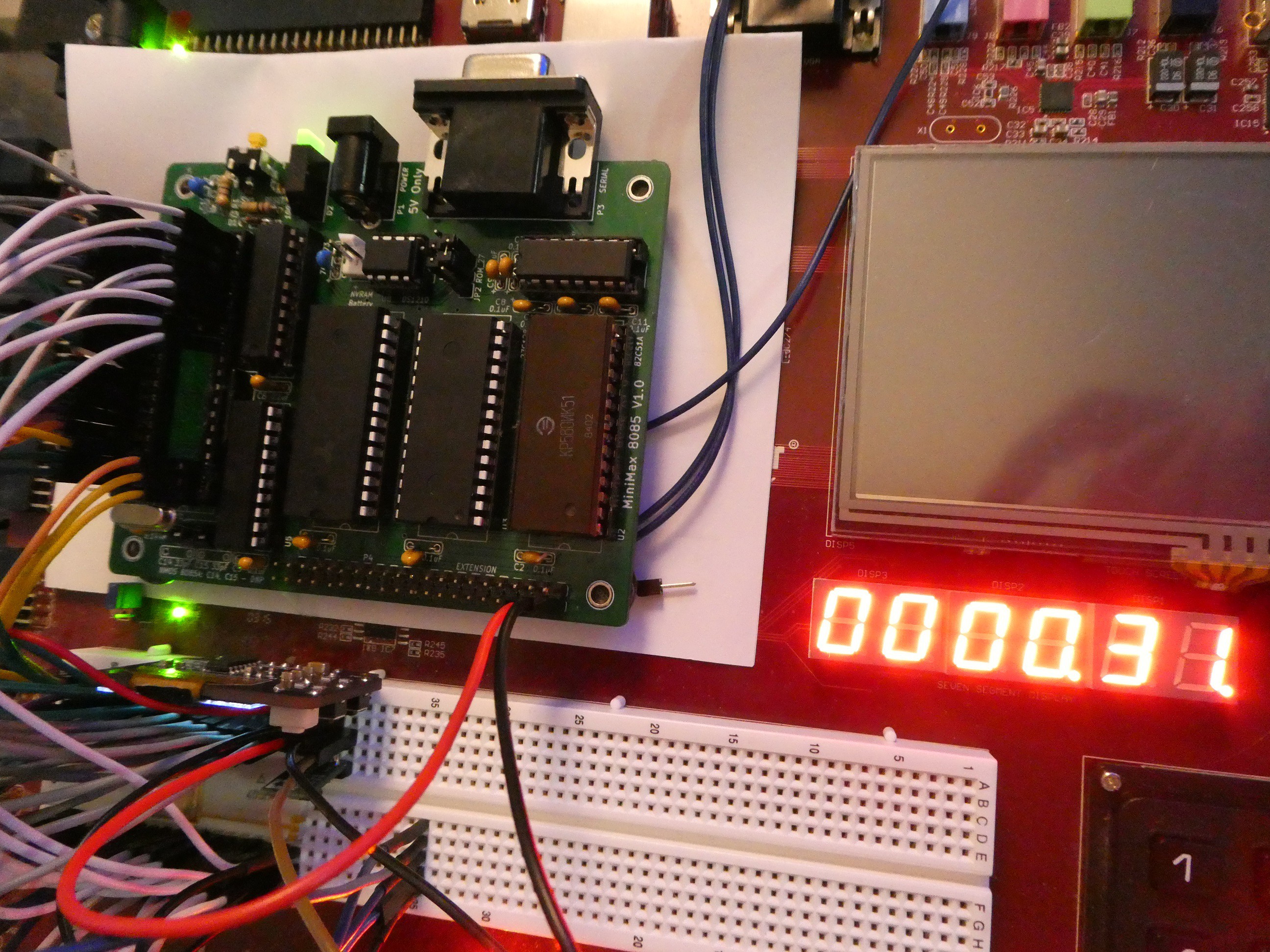
I decided to "re-wire" the FPGA to SBC for sort of custom "in-circuit emulator":
- Move the CPU from SBC to FPGA breadboard
- Wire one set of signals from breadboard to CPU socket on SBC (only those that are needed, for example SID/SOD etc. are not critical)
- Wire another set of signals from CPU to FPGA. These include address, data, and some control signals - these are "read-only" for FPGA as it is only "listening" to the state of CPU signals and displays/logs them.
- Drive CPU's READY signal - READY low puts the CPU in the wait state which can last indefinitely. During this time most control signals are in "frozen" state.
CPU is surrounded by wires, many pins have 2, one to SBC another to FPGA:
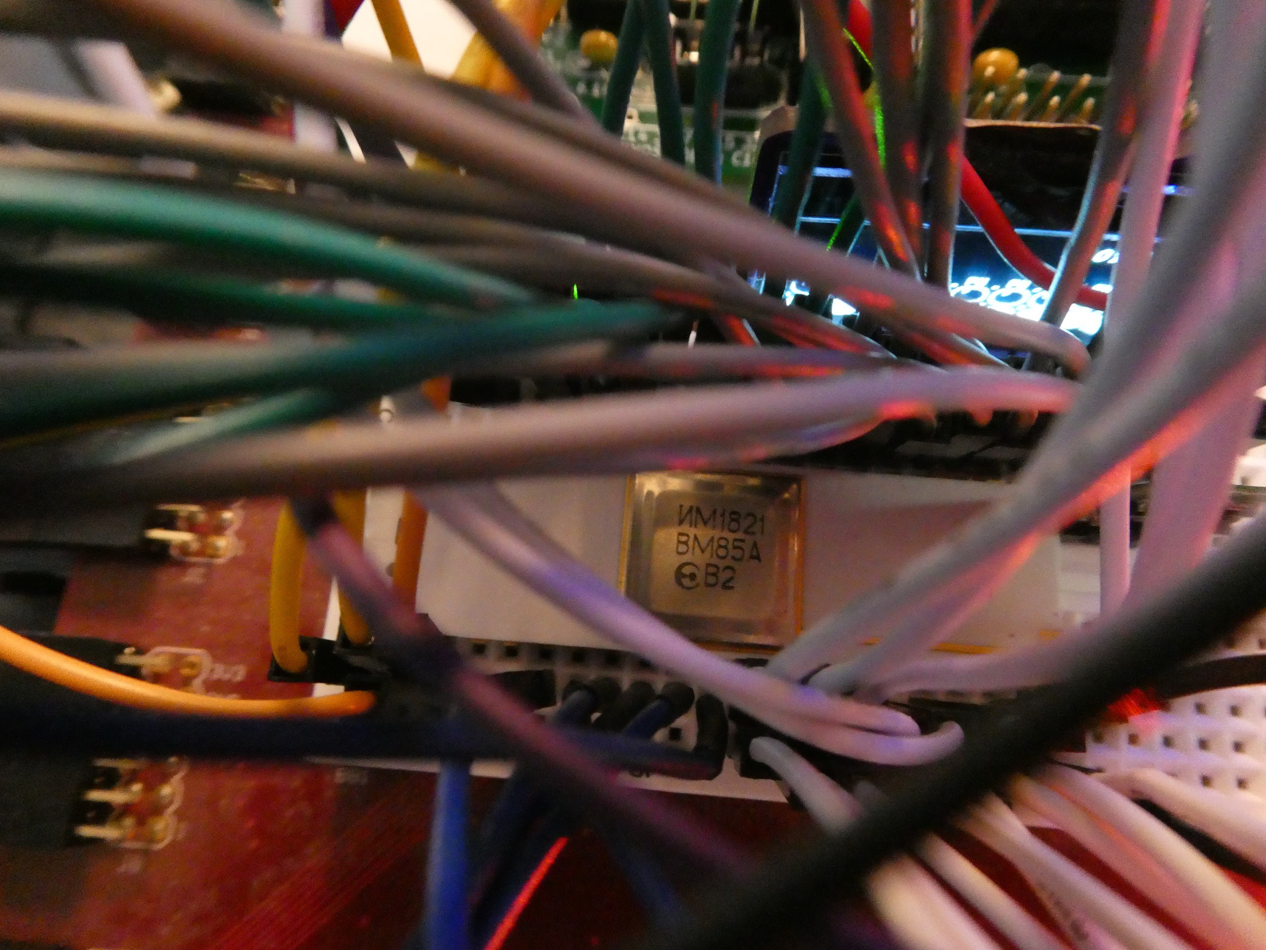
Overall connection is messy, but works (including the 6.144MHz crystal which is pretty removed from CPU XTAL pins against all recommendations)
With these connections, I went on to write a new FPGA design, with reusing much of the components I already had.
The key idea is to:
- spy on the machine cycle appearing on the bus (IO/nM, S1 and S0 signals are used for this, refer to 8085 documentation)
- be able to select any (or none, so CPU runs at full speed) of machine cycles of interest, and if hit, drive READY low
- while READY is low, pick up the state of CPU signals of interest (address, data buses) and display them on VGA and serial terminal (reusing existing components)
- When all signals are displayed, wait for manual "continue" signal (simple button click, or it can be held down)
- Based on what is seen, figure out the bug
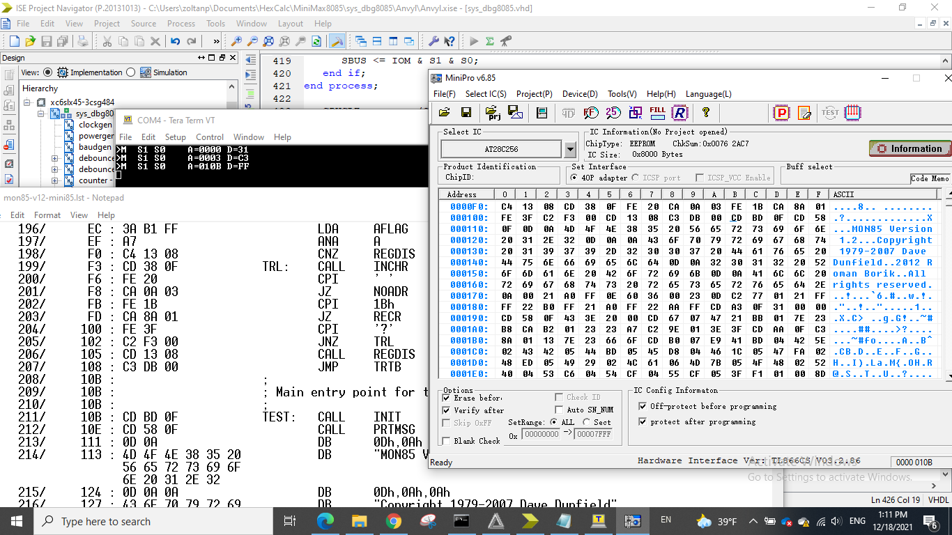
1 - 4 above worked great (and that's why I am documenting as it can be useful for other hobbyists) but I failed at 5. I see the bug, but not yet sure what is causing it.
In the boot sequence, jump to 0x010B is successful, but at that location CPU reads 0xFF (RST 7) instead of 0xCD (CALL) - RST 7 of course calls into interrupt vector entry point (0x0038) and executes that instead of the required init routine. The AT28C256 contains the right value at that address (as read by legendary TL866). I observe with simple volt meter (at this point all signals except CLK are frozen) /OE and /CS low, but all data bus high.
Bug or not, it is fascinating to observe CPU in action, going through its cycle exactly as it is described.
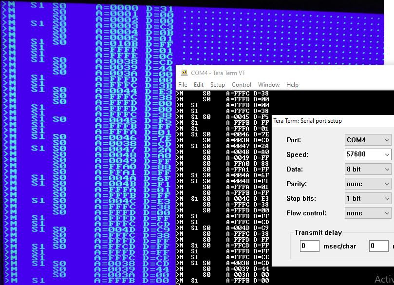
Session with only instruction fetch traced (IO/nM & S1 & S0 = "011")
And a session with all memory access traced (IO/nM & S1 & S0 = "0XX")
The core of the design are 2 registers ("process" in VHDL parlance). The first register captures the machine state and trailing edge of ALE (same moment multiplexed AD bus has the address bits A7 .. A0):
-- capture low address bus as ALE goes low
on_ALE: process(ALE, DBUS)
begin
    if (falling_edge(ALE)) then
        ABUS(7 downto 0) <= DBUS;
--        "SBUS" is handy 3-bit indicator of the access;
        SBUS <= IOM & S1 & S0;
    end if;
end process;
Note that SBUS can only have 8 discrete states, as described here:
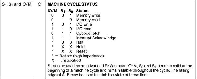
These states are evaluated at each CPU clock cycle (which is also spied on by the FPGA) and rdy_ff (ready flip-flop) state updated:
on_CPUCLK: process(CPUCLK, SBUS, reset)
begin
    if (reset = '1') then
        rdy_ff <= '1';
    else
        if (falling_edge(CPUCLK)) then
            if ((thaw and button(0)) = '1') then
                rdy_ff <= '1';
            else
                rdy_ff <= not switch(to_integer(unsigned(SBUS)));
            end if;
        end if;
    end if;
end process;
At RESET or when "thaw" (tracer has finished displaying the bus status record) or "continue" button(0) is pressed, READY should go high, and if switches select any of the desired machine state to be inspected, it should go low. Setting all switches low means there will be no match with any of the 8 different possible machine states, and CPU will not be stopped.
When READY is high, that is also a RESET signal for the tracer component. So when CPU runs, tracer is frozen, and vice versa. Once READY goes low, tracer can start going through a sequence of outputting values picked up from the bus:
tr: tracer Port map (
            reset => rdy_ff,
            clk => baudrate_x1,
            start => freq_2048(6),
            continue => not freq_2048(6),
            data(15 downto 0) => ABUS,
            data(23 downto 16) => DBUS,
            data(31 downto 24) => X"00", -- not used
            flags(7) => nINTA,    -- trick to display 2 characters per 1 flag
            flags(6) => nINTA,
            flags(5) => S0,
            flags(4) => S0,
            flags(3) => S1,
            flags(2) => S1,
            flags(1) => IOM,
            flags(0) => IOM,
            tracechar => tracechar,
            tracechar_send => tracechar_send,
            trace_done => thaw
        );
The tracer outputs single ASCII character at a time on tracechar port, and when the character is ready asserts tracechar_send high. Both the UART sender and TTY2VGA are driven by these signals so there is simultaneous output to both:
The tracer component reads the state of signals of the stopped bus, converts them to a stream of ASCII characters and drives the output to TTY or UART. It is not much more than a counter that goes character by character passed in as "traceformat". If the character is printable ASCII (0x00-0x7F) it is output verbatim. However if it is in the range 0x80-0x87 address and data bus values are picked up in 4-bit nibbles to be displayed as HEX, and if in range 0xC0-0xC7 single flag bits are resolved into ASCII characters using the flag2char lookup table passed in:
tr: tracer
        Generic map (
            traceformat => (
                get_byte('>'),
                X"C0",
                X"C1",
                get_byte(' '),
                X"C2",
                X"C3",
                get_byte(' '),
                X"C4",
                X"C5",
                get_byte(' '),
                X"C6",
                X"C7",
                get_byte(' '),
                get_byte('A'),
                get_byte('='),
                X"83",
                X"82",
                X"81",
                X"80",
                get_byte(' '),
                get_byte('D'),
                get_byte('='),
                X"85",
                X"84",
                get_byte(' '),
                X"0A",    -- LF
                X"0D",    -- CR
                X"00",    -- done
                X"00",    -- done
                X"00",    -- done
                X"00",    -- done
                get_byte(' ')    -- last entry must be !=0
                ),
            flag2char => (
                get_byte('M'),    -- flag 0, value 0
                get_byte(' '),
                get_byte(' '),
                get_byte(' '),
                get_byte(' '),
                get_byte(' '),
                get_byte('I'),
                get_byte('A'), -- flag 7, value 0
                get_byte('I'),    -- flag 0, value 1
                get_byte('O'),
                get_byte('S'),
                get_byte('1'),
                get_byte('S'),
                get_byte('0'),
                get_byte(' '),
                get_byte(' ')    -- flag 7, value 1
                )
        )
        Port map (
            reset => rdy_ff,
            clk => baudrate_x1,
            start => freq_2048(6),
            continue => not freq_2048(6),
            data(15 downto 0) => ABUS,
            data(23 downto 16) => DBUS,
            data(31 downto 24) => X"00", -- not used
            flags(7) => nINTA,    -- trick to display 2 characters per 1 flag
            flags(6) => nINTA,
            flags(5) => S0,
            flags(4) => S0,
            flags(3) => S1,
            flags(2) => S1,
            flags(1) => IOM,
            flags(0) => IOM,
            tracechar => tracechar,
            tracechar_send => tracechar_send,
            trace_done => thaw
        );
Discussions
Become a Hackaday.io Member
Create an account to leave a comment. Already have an account? Log In.