 Timo
TimoLFO I will be used to modulate the frequency of the main voice oscillator.
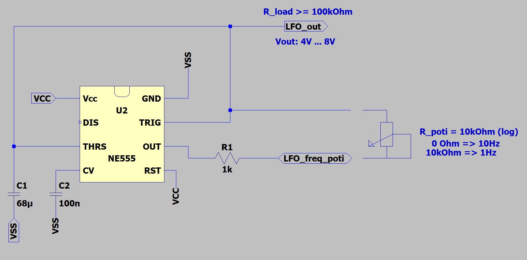
The operating principle is pretty much the same as for the main voice oscillator. Capacitor C1 is charged through R1 up to 8V. This triggers the NE555 to set the pin OUT to 0V and C1 is discharged down to 4V. the NE555 sets pin OUT to 12V and the cycle repeats.
The charging and discharging creates a sort of triangular signal voltage over C1. This will be used to modulate the main voice oscillator and generate continuous frequency sweeps.
To not interfere with the charging and discharging cycle, the resistive load put at LFO_out must be significantly higher than R1 and the poti. The load resistance should be at least 10x bigger.
C2 is just buffering the internal voltage divider of the NE555, nothing fancy here.
Discussions
Become a Hackaday.io Member
Create an account to leave a comment. Already have an account? Log In.