 Timo
TimoThis update shows the final state of the testbench i used to test the main voice oscillator and the LFO.
There ...
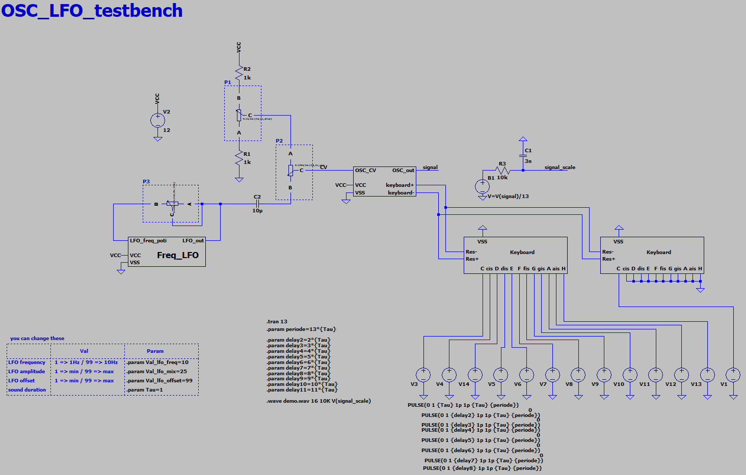
The block in the middle is the main voice oscillator. The LFO supplies the main voice oscillator via a Bias Tee with the control voltage for the frequency modulation. The voltage divider R1, R2 and P1 set a dc control voltage between 4V and 8V. The signal from the LFO couple through C2 and is superimposed on the dc control voltage. The amplitude of the ac part can be set by the poti P2.
Because the output of the LFO and the voltage divider are in the single kOhm range and P2 is at a 100kOhm no buffer or voltage follower is needed.
The two blocks on the right simulate the keyboard. They connect and disconnect resistors depending on the inputs C to H. Each block contains one octave.
B1 is a voltage controlled voltage source and just decreases the main voice oscillator's signal by a factor of 13 because the export to a .wave file only works for signals between +1V and -1V.
You can find all simulation files in the folder OSC_II_tb.zip. After simulation you can find demo.wave in the simulation folder and can listen to the synteziser. You can change the LFO settings in the box in the lower left corner.
Discussions
Become a Hackaday.io Member
Create an account to leave a comment. Already have an account? Log In.