 Timo
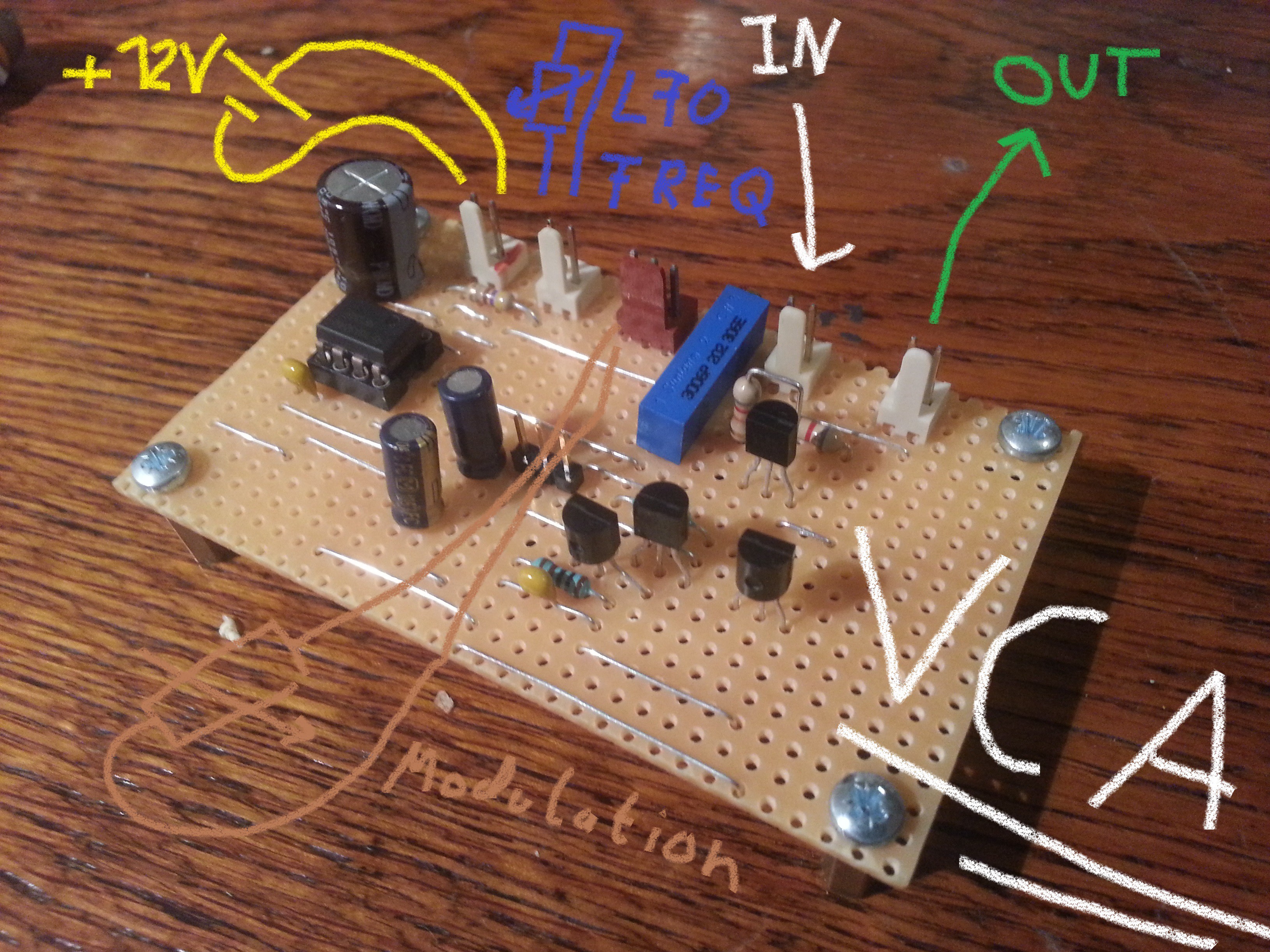
TimoThe VCA and it's LFO are finished and they work great.
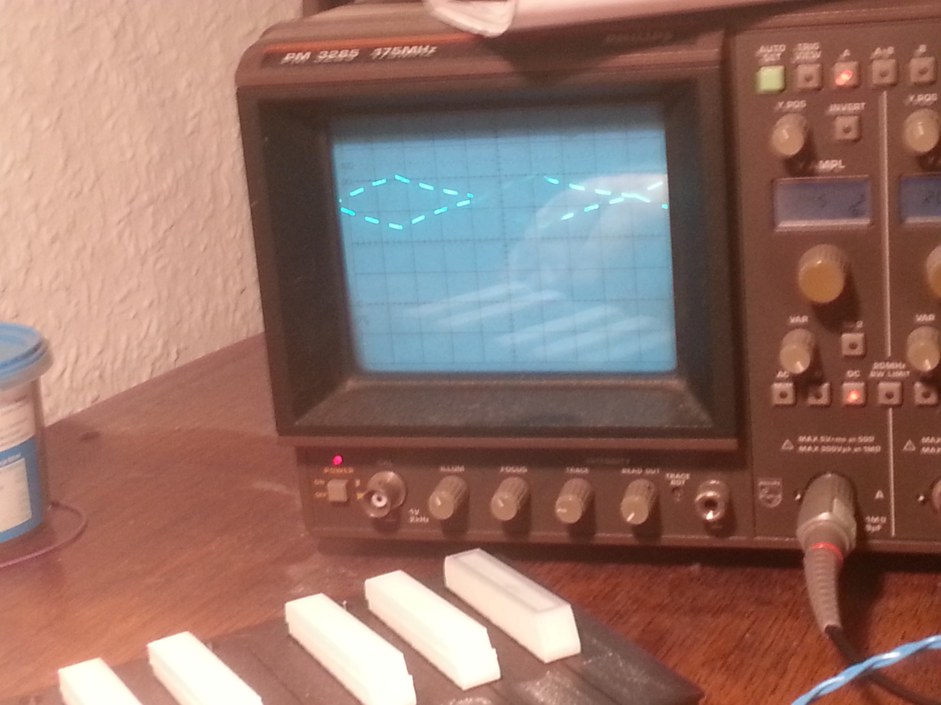
The resulting waveform can be seen down below. Because of the low frequency of the LFO the waveform is a bi....t hard to capture on camera.
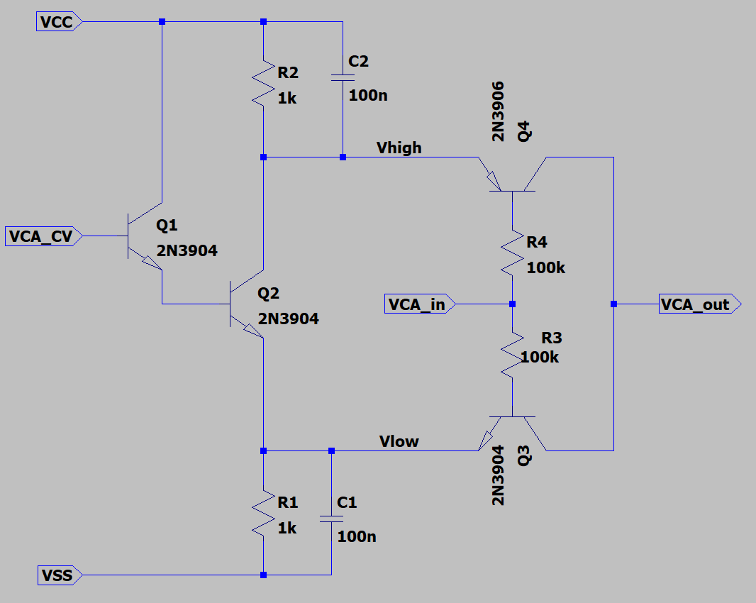
A small bugfix was needed. A revised schematic is shown down below. The input current of Q2 is roughly 10µA. The output resistance of the bias tee which supplys VCA_CV is between 1kOhm and 100kOhm. (Not a great voltage source.) Therefore there is a DC shift of VCA_CV between 0V and 1V depending on amount of amplitude modulation.
This results in a noticable lower volume when there is no amplitude modulation. Not a biggy but annoying enought to make me fix it.
Q1 acts as a buffer for Q2. Q1 decreases the input current by its current gain which is roughly 30 in this operationg point.
So far the main components of the Synthe555er are done. But some stuff is missing. Next I will add a simple lowpass filter and buffer to drive a line output or maybe a headphone.
Discussions
Become a Hackaday.io Member
Create an account to leave a comment. Already have an account? Log In.