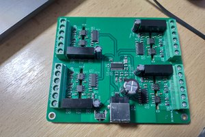
This project is effectively a combination of my TTL USB UART board, itself based around a CY7C65213 USB UART chip, and half of the isolated USB null modem project.
The isolators of choice are the SI8035 and SI8055. They're the same, except that one has 3 channels and the other 5. That's because there are 3 transmit channels (TXD, CTS and DTR) and 5 receive channels (RXD, RTS, DSR, DCD and RI). In addition to this, 5 volts from the USB bus is passed to the target side with an isolated DC-to-DC converter module. The 5 volt output is run through an LDO to make 3.3 volts and both the 5 volts and 3.3 volts are selected with a solder jumper and the selected voltage becomes both the supply voltages for the isolators (which also makes them the voltage level for the resulting signals), and is passed through an AP2331 protector to the V+ pin of the target connector.
The 5 volt input to the DC-DC converter is switched on and off with a P-MOSFET and the power enable signal from the UART chip.
As with the isolated null modem, the ground planes on the primary and secondary sides are kept as far apart as possible. The DC-DC converter chip has the primary and secondary side pins closer together than that, so to improve the creepage distance there, a slot is cut between them.
 Nick Sayer

 CentyLab
 Jakob Faltisek