 NanoCodeBug
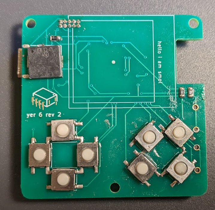
New PCBs arrived! Just in time to assemble another prototype before the holidays. Still learning how to do SMD soldering with hot air. I cleaned up the PCBs later, but here it is almost complete. Feels like it's still easier to solder the larger chips with an iron than with hot air at the moment. Hot air makes getting the 805 sized parts a lot easier to seat nicely though.
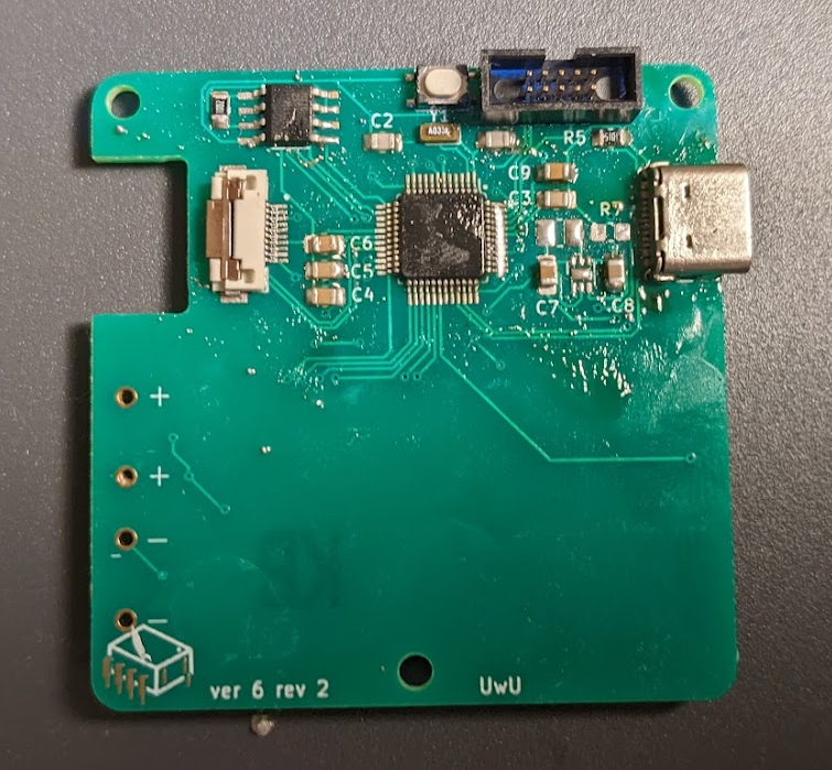
Unfortunately, this board has a major flaw, highlighted below. I've accidentally flipped the data positive and data negative. Everything else works though! I won't be able to work with this prototype as a MSC device, but programming and debugging over jtag works fine. I'll remove the battery socket and add headers for attaching the CurrentRanger.
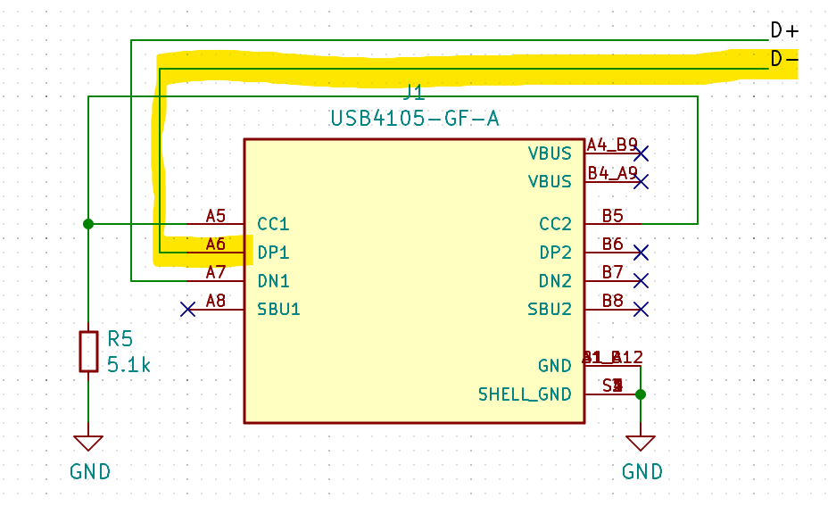
Next revision will have the mosfet for toggling the voltage divider, as well as an updated usb-c circuit, to be more compliant with the detect lines both getting resistors, and the D1 and D2 lines being paired together. As well as a resistor to simulate load on the usb 5v line, for devices that refuse to start data communication unless power draw is detected.
Discussions
Become a Hackaday.io Member
Create an account to leave a comment. Already have an account? Log In.