 Tim
TimNow that the design topics have been fixed and the circuit works in simulation, we can continue to generate a layout. Again, using PCBflow will output a preliminary PCB with placed components:
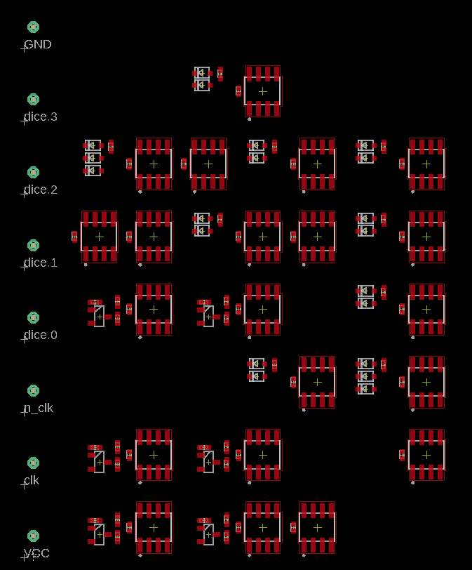 The statistics are as follows:
Microcell counts:
ne_NOT      21
ne_WAND2     7
ne_TBUF      6
ne_WAND3     2
Component usage
Component           Count

pin                 8
NE555               21
cap                 21
resistor            27
diode               20
npn transistor      6
------------------  -----
Total:              103
Well, i'd say it's a bit more than a dice with the old role-models of NE555 and CD4017 require, but who are we to judge? Still small enough to comfortably build and test.
Still some work to do manually: Add the LEDs for the dice, add the CD4017 clock generator footprint, add groundplane and let the autoroute do its (admittedly gut-wrenching) job.
And here we are, with a nice simulation of the full PCB. A modern rendition of the classic NE555/CD4017 based electronic dice.
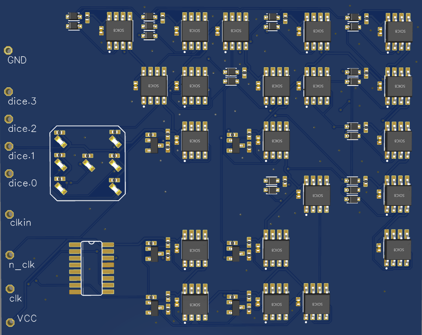 PCBs are being made now and should arrive soon.
Discussions
Become a Hackaday.io Member
Create an account to leave a comment. Already have an account? Log In.