 AlliedEnvy
Using our truth table, we can derive several logic gates using 555s. For combinational logic, we want to avoid any states where the RS latch remains unchanged (i.e. where Set and Reset are both 0).
| !R | CE | C | Th | !Tr | Set | Reset |
|---|---|---|---|---|---|---|
| 0 | x | x | x | x | 0 | 1 |
| 1 | 0 | x | 1 | 1 | 0 | 1 |
| 1 | 0 | x | 0 | 1 | 0 | 0 |
| 1 | 0 | x | x | 0 | 1 | 0 |
| 1 | 1 | 0 | 0 | x | 0 | 0 |
| 1 | 1 | 0 | 1 | x | 0 | 1 |
| 1 | 1 | 1 | x | 0 | 1 | 0 |
| 1 | 1 | 1 | x | 1 | 0 | 0 |
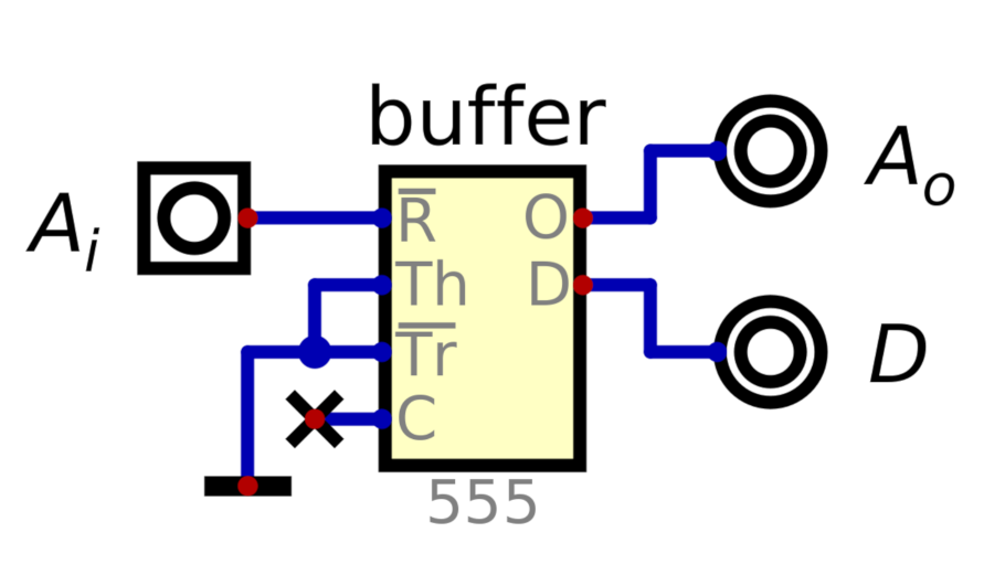
The most basic are the 1-input gates, the buffer and the inverter.
Since !Reset drives the output low, we can put the other inputs in a state to (otherwise) drive the output high, and use !Reset as the input for our buffer. Let's pull Tr and !Th low and leave C floating. The result:
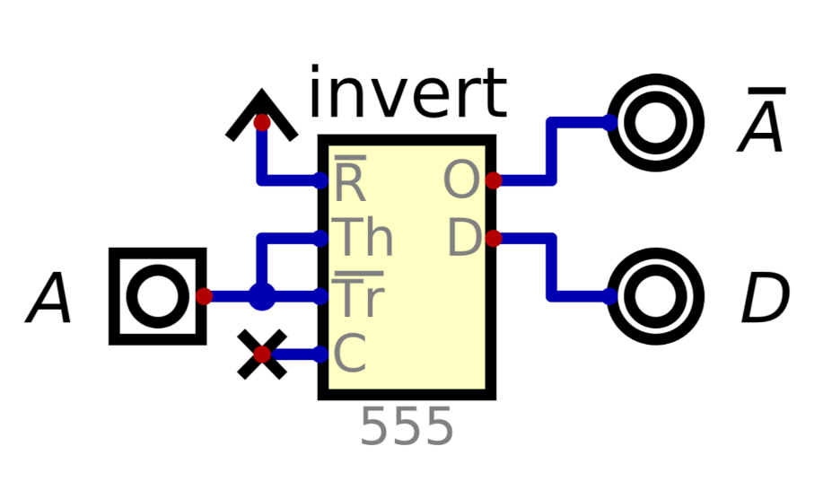
For the inverter, we can tie !R high and tie Th and !Tr together as the input:
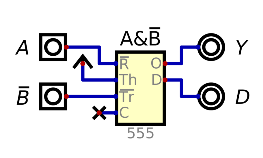
Next, we'll do a 2-input gate. It would be nice to have a functionally complete gate. We can combine our buffer and inverter to create an inhibit gate, A&!B, which is functionally complete. I'll be calling this ANDN for brevity's sake.
Finally, since the Discharge pin is open-collector, we can tie multiple Discharge pins together with a pull-up resistor to make a wired-AND for almost free.
We could explore other gates, but this is enough.
Discussions
Become a Hackaday.io Member
Create an account to leave a comment. Already have an account? Log In.