0%
0%
FFCPStep
Low cost TMC2208 board for the FlashForge Creator Pro
 leo60228
Become a Hackaday.io member
Already have an account? Log in.
Just one more thing
To make the experience fit your profile, pick a username and tell us what interests you.
Pick an awesome username
hackaday.io/
Your profile's URL: hackaday.io/username. Max 25 alphanumeric characters.
Pick a few interests
Projects that share your interests
People that share your interests
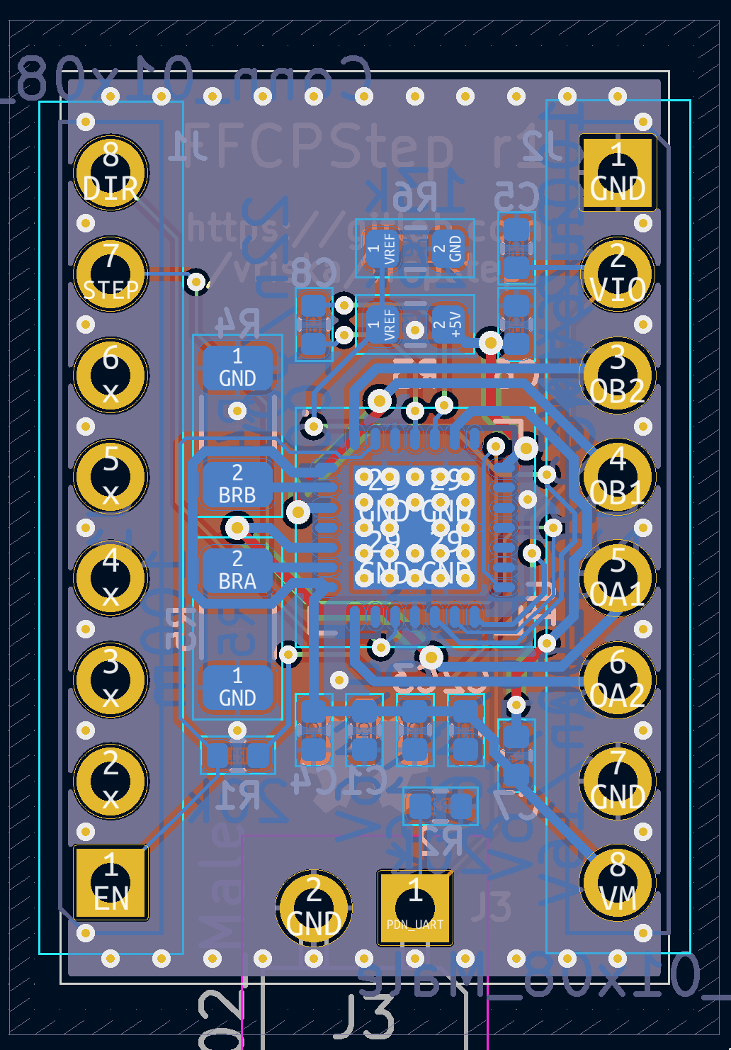
 It looks nice from the front, though:


 Josh Kittle
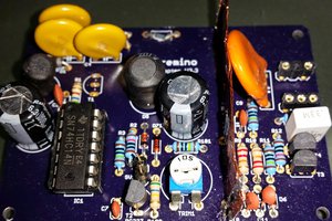
 Christoph
I know this may seem very random but how did you get the crossing "wires" in the schematic without a connection or node being generated there? Mine always want to show a junction.