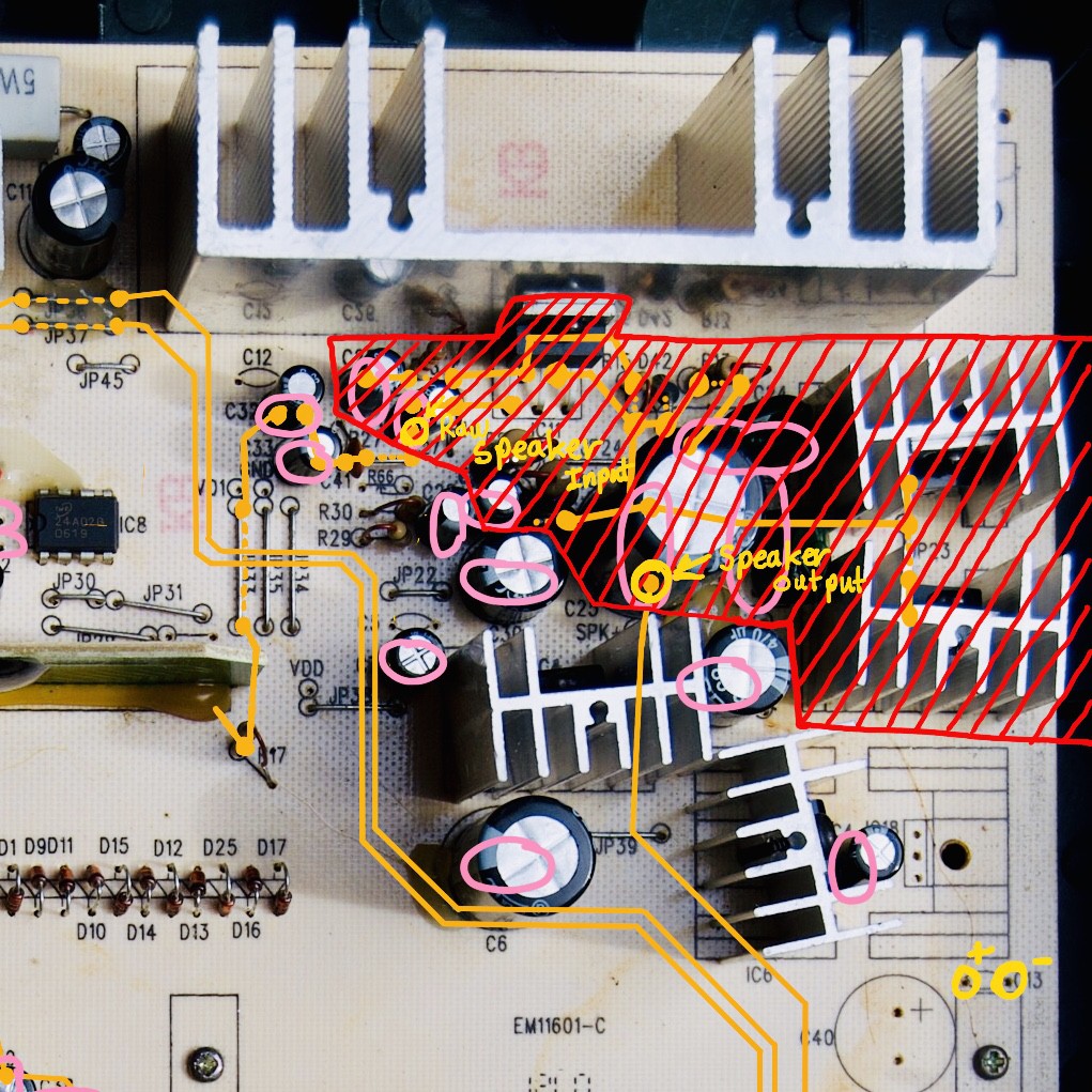
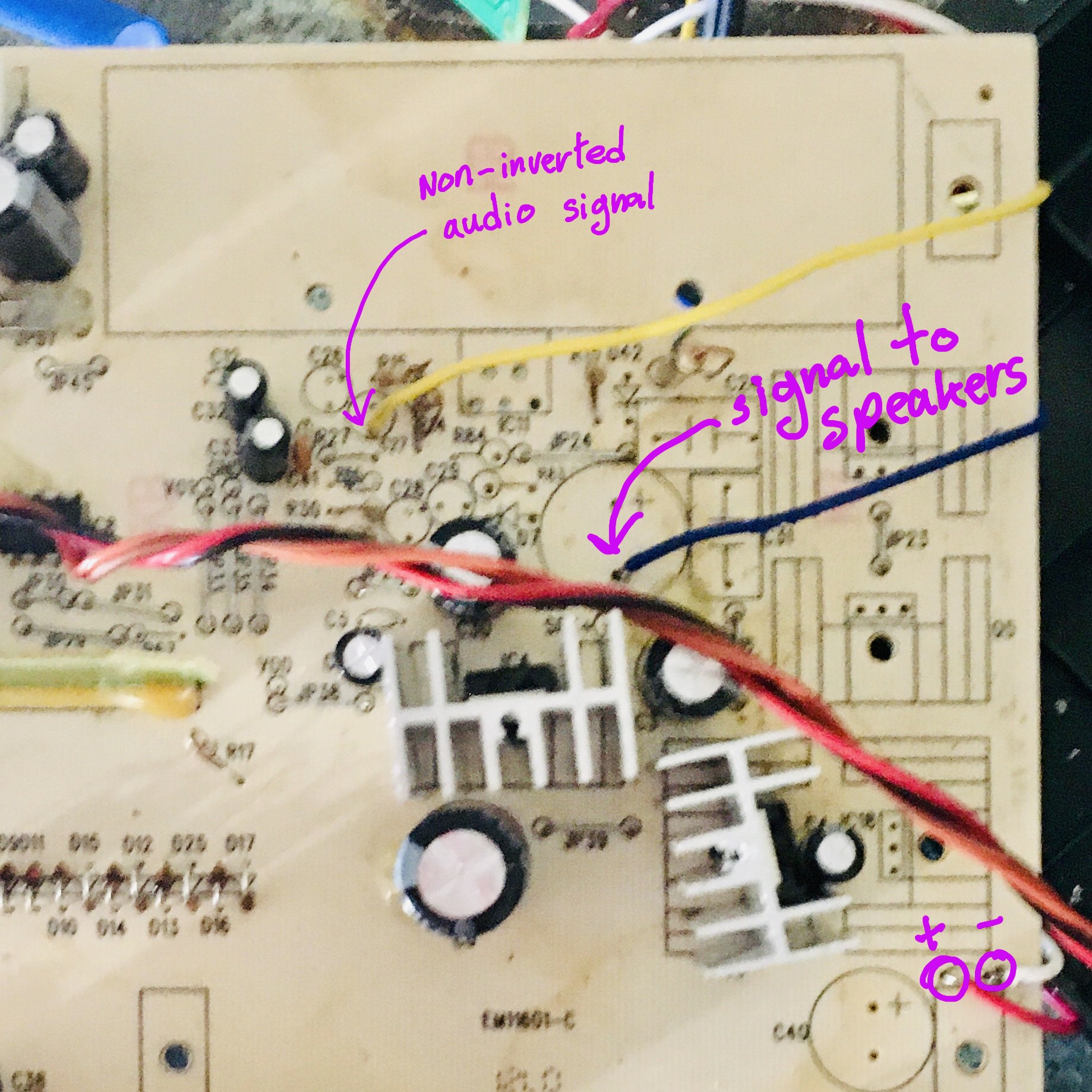
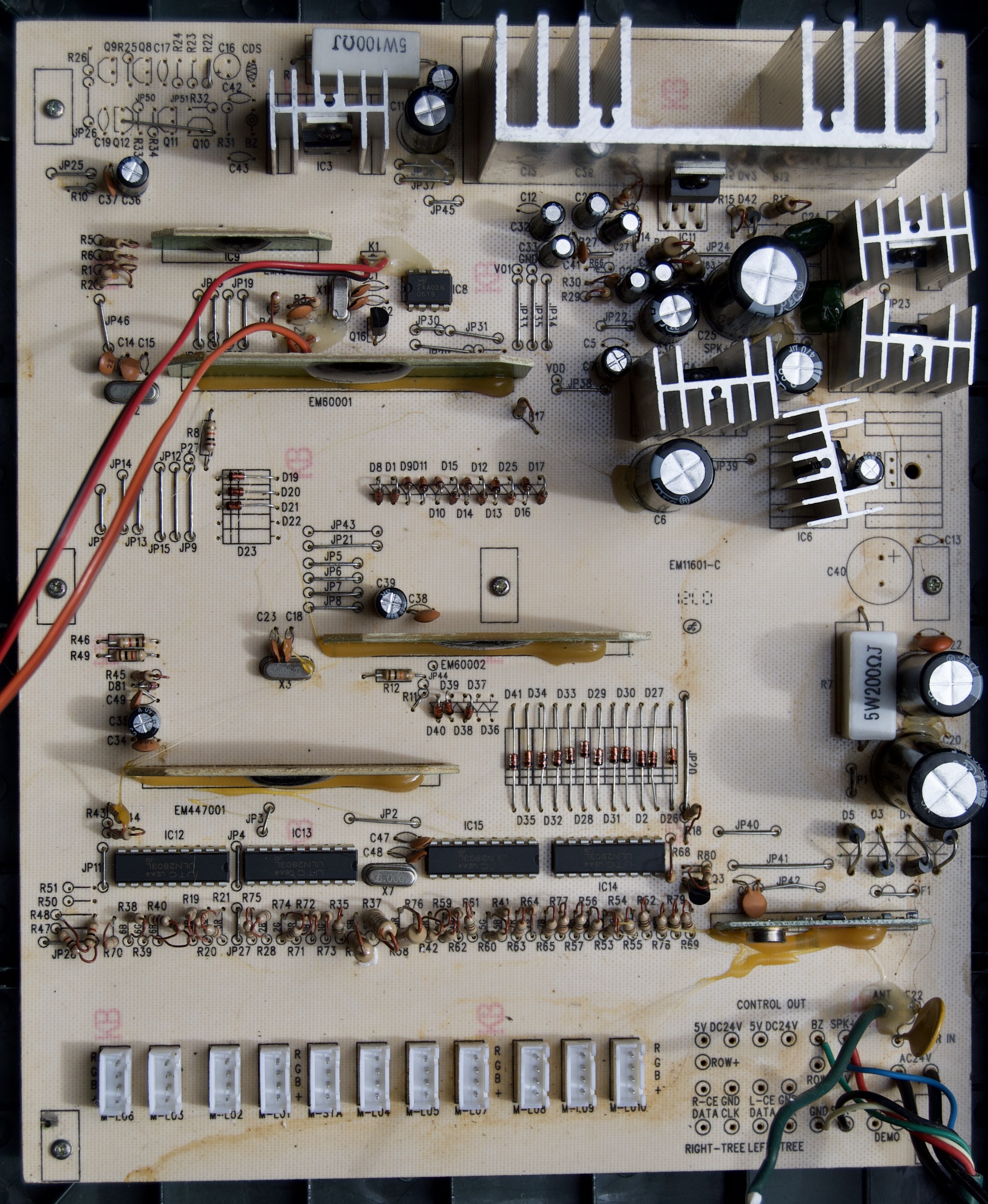
Fixing the Gemmy 7 1/2 foot Incredible Holiday Lightshow tree.
To make the experience fit your profile, pick a username and tell us what interests you.
We found and based on your interests.
It has been a while. I finished this project last Christmas. After testing the board, I couldn't determine which audio component was broken. So, I replaced the whole audio board circuit and it works great now. To replicate the process, everything in the shaded area must be removed. Save the big heat sink because we will need it later.
I purchased a TDA2030A Amplifier Board DIY Kit from Amazon. I populated the right-hand side of the board. I did not use the audio input jack and horns because I soldered directly to their pins. I also didn't solder the potentiometer and LED. When finished I used the heat sink from the mainboard and connected it to the TDA2030A on this module. You will need to drill one hole in the module's board. The hole placement will be through the circuit of the unpopulated left-hand side. Secure the attached the module's board with a screw. I used Loctite but this may be overkill since the TDA2020A is also screwed to the heat sink.
Solder to the following points on the board. The audio input signal on the audio module is connected to the lower pin at C27 on the mainboard. The audio output signal from the audio module gets connected to the negative pin where the large 2200nF capacitor once sat. Power to the audio module is connected to unpopulated capacitor pins shown in the lower right-hand side of the photo below.
Now for the moment, you have all been waiting for, putting it together. If you did everything correctly, all you need to do is flip the audio module upside down and line up the large heatsink's top holes with the mainboard's heatsink holes and screw it on. Please make sure that nothing from the audio module is touching anything on the mainboard except the large heatsink and the wires connecting the two boards. Test and enjoy! The tree sounds better than ever and nostalgia lives on.
After the winter holidays, I plugged a new 24v DC 3a power supply into the tree and it worked. The only issues now are that the lights seem to get a bit dim when the tree's bulbs try to display a color that uses two or more of the LEDs to create. This was expected because the original power supply was 24v AC at less than an amp. That was converted into about 36v DC on the circuit board and that fed the 24v DC regulator that lit the LEDs. The board is only getting about 23v of power. That is being reduced further by the 24v DC regulator as it tries the impossible task of maintaining 24v DC. I'm going to pop it out and bridge the connection. This should solve the issue. I should also mention that there is a good and bad way to plug the tree's power connection into the provided barrel jack connector. Make sure the notch is pointed up. Otherwise, you are looking at losing a few additional volts.
I swapped out the audio amplifier (TDA2030AL) and the two transistors (TIP41C and TIP42C) attached to it with replacements and the problem persists. I desoldered the sound system components and attached an external TDA2030AL soundboard but the problem persists. I soldered in a new thermistor for good measure and it solved nothing. I think it might be the power supply. I took some time and traced out the components on the board. I will have to wait for a new power supply to arrive.
I unscrewed all the screws that line the edge of the main control module plus a few screws that helped hold the wire cover in place. I probed the board and discovered that there is a voltage drop from 33 volts DC to about 6 volts DC when the lights go out and the audio gets garbled. The thermistor, on the bottom right-hand side of the board, is being used as a self-resetting fuse for overcurrent protection. It is heating up and dropping the voltage on the board. There must be a short somewhere. I tested all the diodes, capacitors, voltage regulators, and the audio amplifier. I suspect that it is possibly the audio amplifier (TDA2030AL) and/or the transistors (TIP41C and TIP42C) that are attached to it.
I unscrewed the six screws holding the speaker closed to reveal a 4 ohm 20 watt speaker, a 4 ohm 10 watt speaker, and a small controll board for the sensor.
I desoldered the 3.3µF capacitor and speakers. I tested the capacitor for a short, it was fine. I measured both speaker's and their resistance did not indicate any short. With the speakers desoldered, I plugged the speakers back in and started the tree. The lights did not dim this time. I took this to mean that the sensor control board was not causing it, but to be sure, I resoldered the speakers and desoldered the signal (NON), 5 volts (VCC), and ground (GND) wires from the sensor control board and turned the tree on again. This time the lights dimmed, and the audio got garbled after a while. The issue seems like it has to do with the sound system or power supply.
I tested the tree without the speaker connected, and it runs continuously without dimming. Next, I will open the speaker up and test the two speakers and auto-start sensor.
Create an account to leave a comment. Already have an account? Log In.
Become a member to follow this project and never miss any updates