 strange.rand
The module consists of 3 main components:
- PZEM-004T v3.0 – an upgraded version of energy meter
- WT32-ETH01 – well knows ESP32 but with wired ethernet connection
- OLED display (SSD1308 128x64)
A few words about the component choice. WT32-ETH01 was chosen because I don't want to rely on WiFi and need a wired ethernet connection. There are a few alternative bords, but this one is relatively small and cheap. Instead of an OLED display, I'd rather use a color TFT (IPS), but they require an SPI bus that we don't have on WT32-ETH01.
The module should be mounted on a DIN rail, so compatible housing was ordered from Aliexpress.
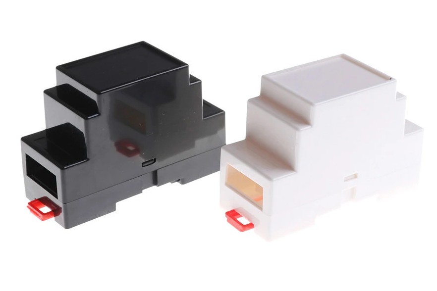
PZEM-004T PCB does not fit into the bottom part of the housing; it is a bit too wide in the middle, where the latch is, though it can be easily fixed with a file.
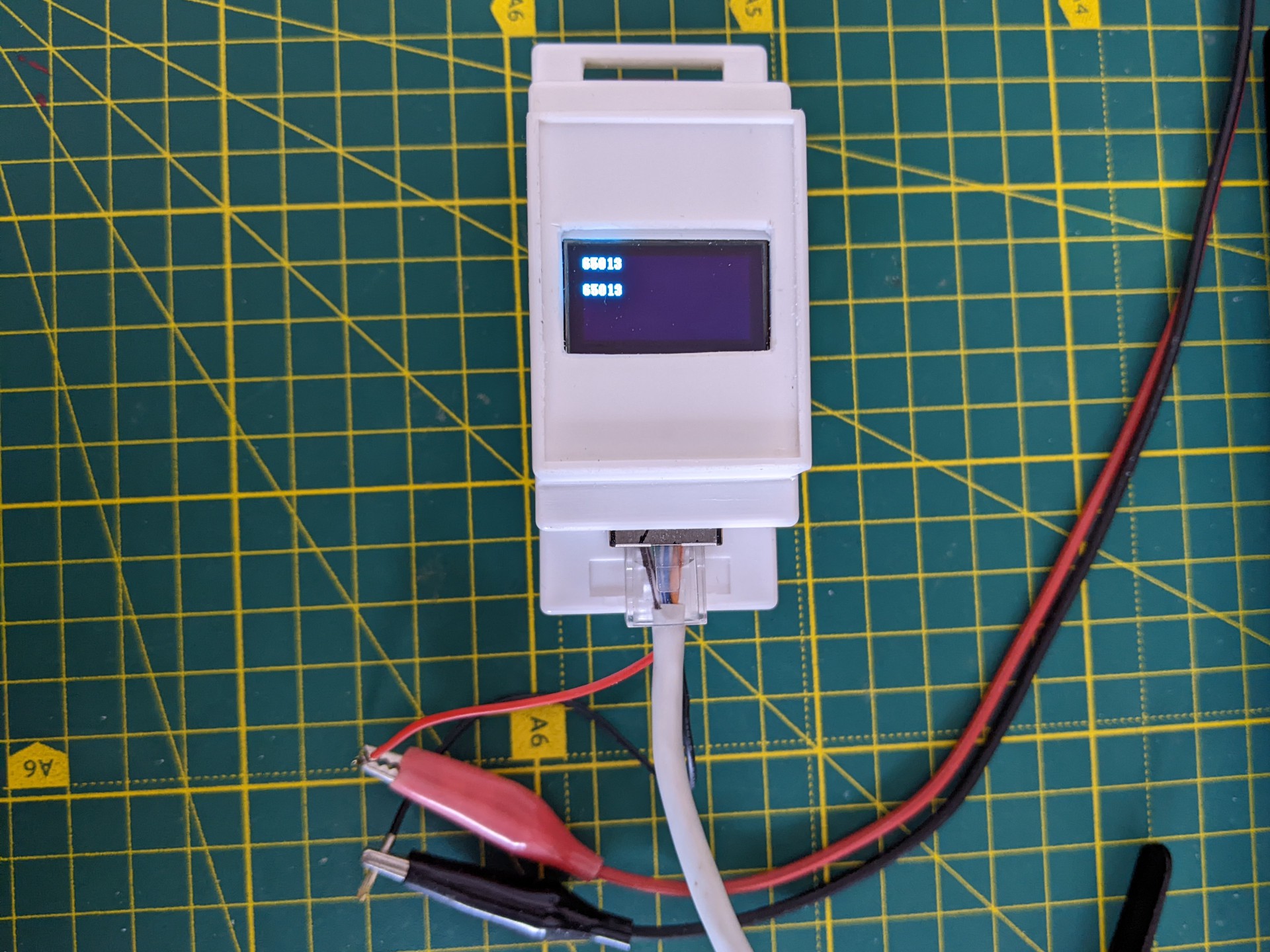
To secure everything in place, I modeled and 3D printed a custom "holder" that you can see in the photo below:
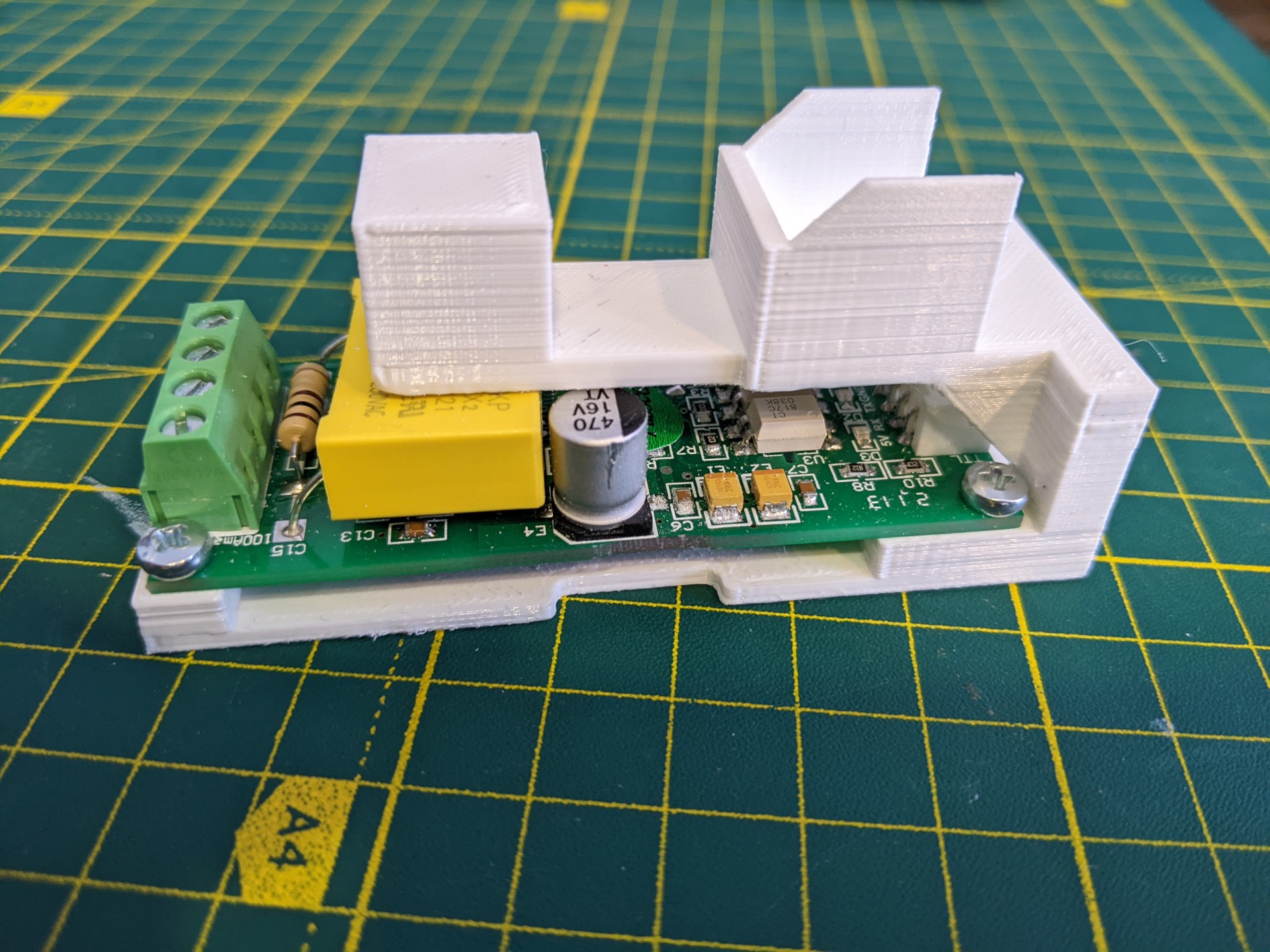
It has holes to screw PZEM-004T PCB, and it also stops WT32-ETH01 from moving around (especially when connecting ethernet cable).
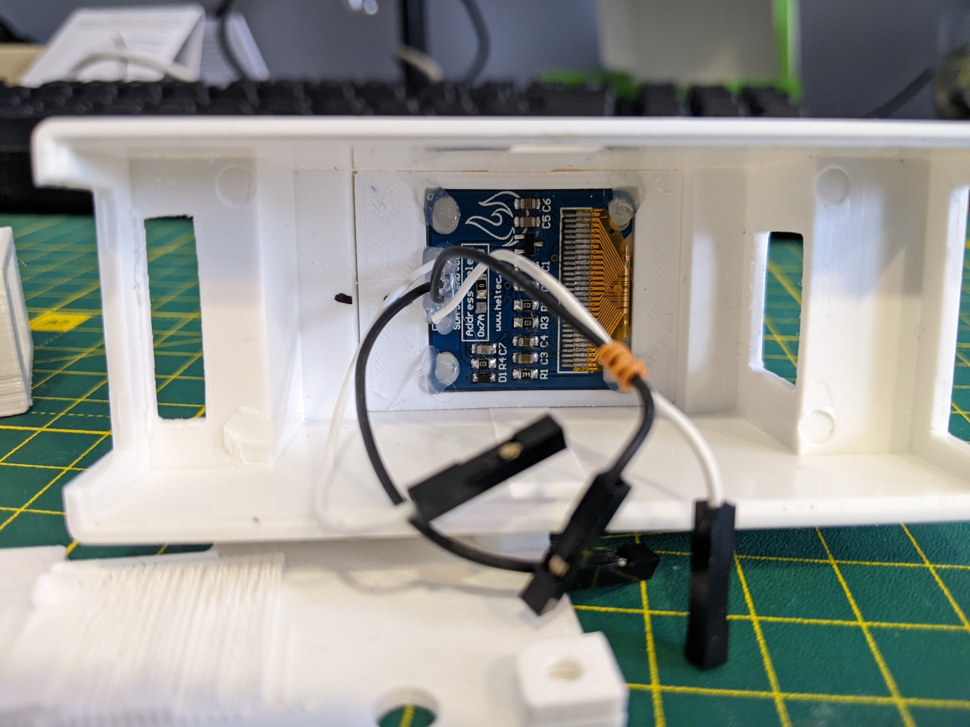
To secure the screen, one more part was 3D printed and the screen was hot-glued to it. Then the whole sandwich was hot-glued to the housing itself. All required holes in the DIN rail housing were made by drill and a file (they are way from perfect).
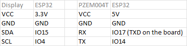
The final part is to wire everything up. I use thin, manually crimped silicon wires for this (also from Aliexpress). Pay attention that RXD pin is not usable on the board, so IO14 was used instead.
Unfortunately, I didn't find a neat way of connecting power to the module, so I just left wires.
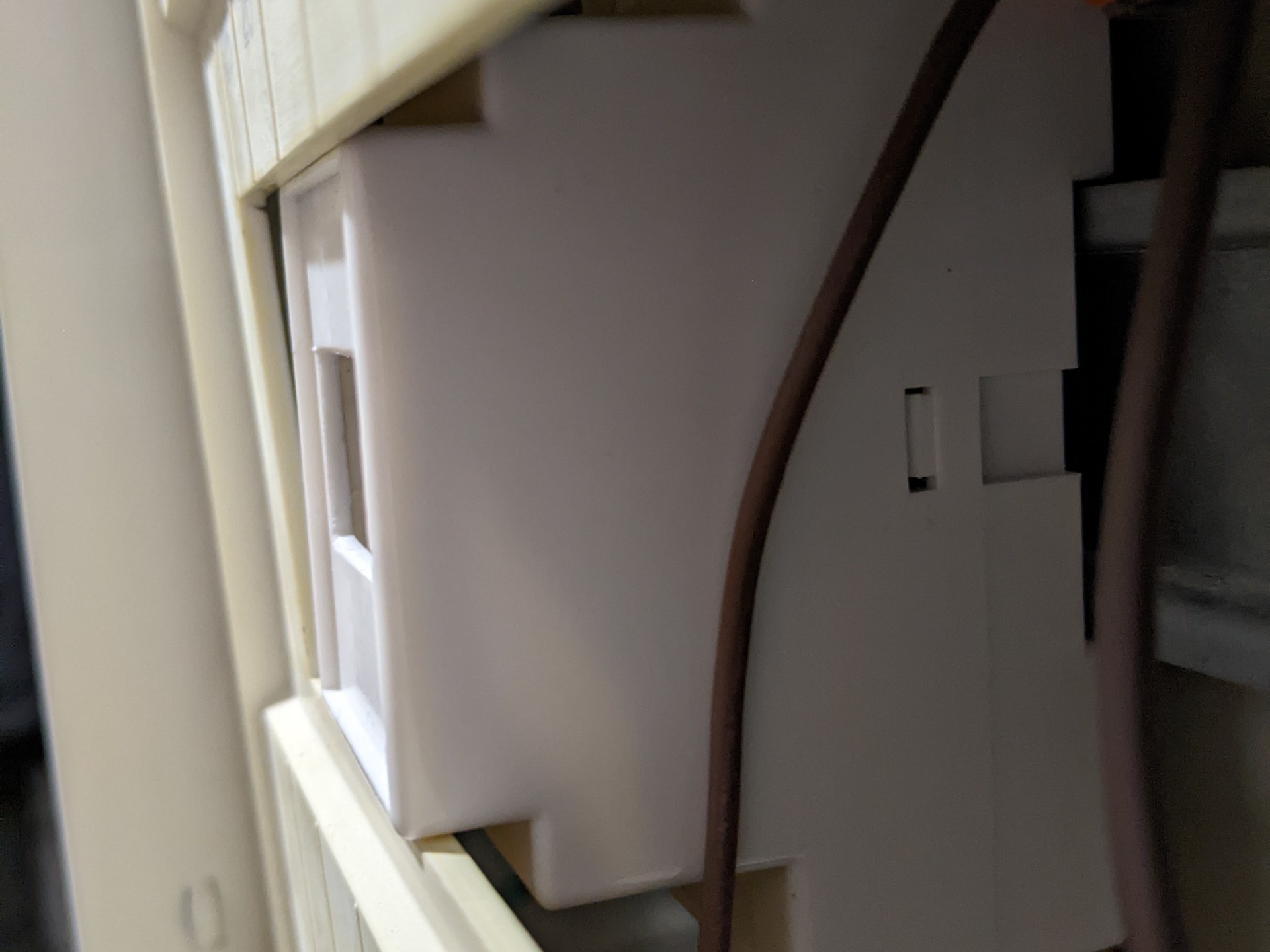
A fun part here. The DIN rail housing is a bit non-standard, so it was impossible to feet it properly in the electric shield. Luckily, this can be fixed with a bit of sanding.
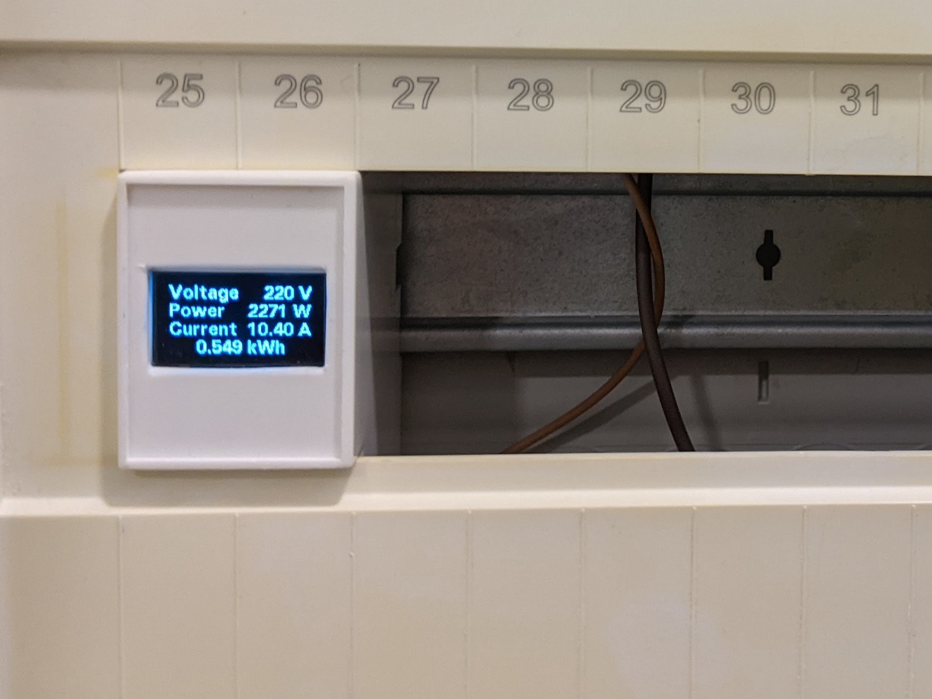
One more thing was planned but forgotten in the process – adding a button or photoresistor, so the screen can be turned off:
- after some period (in the case of using a button)
- when there is on light (in the case of using a photoresistor)
It would significantly prolong the life of the OLED screen.
The next log will be about software, as it is ready to some degree.
Discussions
Become a Hackaday.io Member
Create an account to leave a comment. Already have an account? Log In.