This is a short log about the 7-segment output board. It consists of 12 7-segment digits grouped into groups of two digits for displaying year/month/date/hour/min/sec and a set of 7 discrete LEDs for displaying day-of-week (one LED for each day).
At first, I think I will need to drive each segment separately, but that means 12 driver chips and 7 resistors for every digit. This would be a nightmare to assemble (too many parts and connecting wires). Fortunately, after fiddling with the 74HC595 output stage I found a solution that will let us multiplex these displays!
The segments
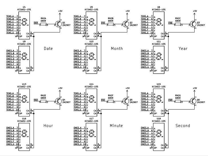
The 7-segment displays part is wired in a pretty basic multiplexing configuration: cathodes connect together and anodes are used to control which set of segments to enable at a time via a PNP transistor. You can see that for each group of 7-segment, I control both anodes at the same time and cathodes are separate into groups of tens digit and ones digit. This will make more sense later.

Days-Of-Week Display
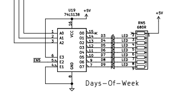
It would be silly to put days-of-week on a 7-segment display showing numbers 1-7 because that's boring. Here I choose the 74LS138 chip to drive 7 LEDs which indicates Monday to Sunday. I wired the 3-bit input of 74LS138 to the lowest 3 bits of the data input because the register that stores DoW could only have values between 1-7 (001 - 111, 3 bits), and also wired the LEDs to output pin 1-7 accordingly. Note that the output is active low so the chip should be used to sink current.

The Data Inputs
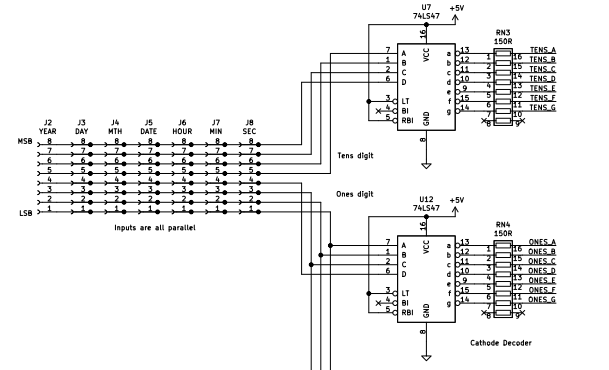
You might remember from the last log that out clock output data of the 7 date-time registers parallelly through 7 sets of 8-pin headers. However, the neat tricks I will talk about later allow us to just tie all of these headers together and select which register would be outputting the data.
Here you can see that we have a pair of classic 74LS47 BCD to 7-segment decoder chips for tens and ones digits. Since DS1302 output data is in BCD format we can directly use the upper 4 bits for tens digit and the lower 4 bits for ones digit.

Where The Magic Happens
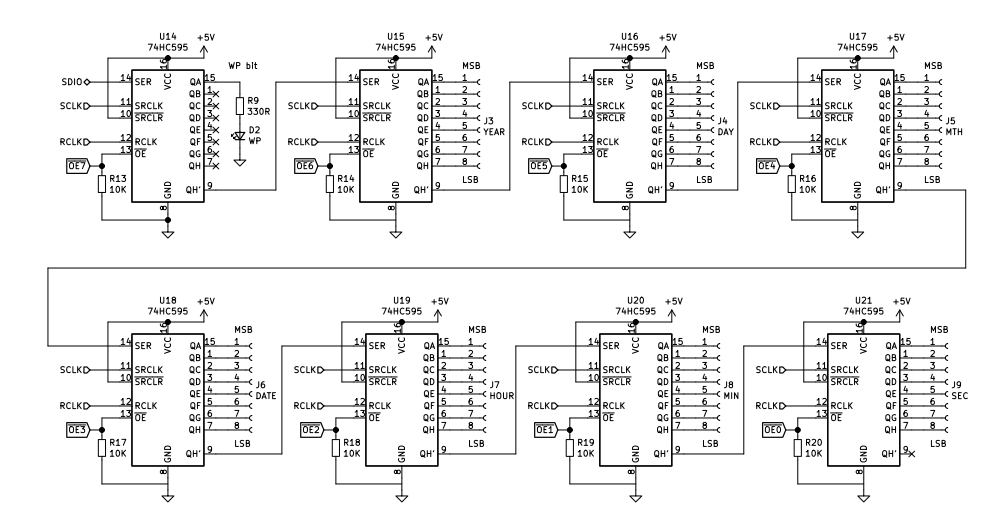
From the last log, you can see that all of the 74HC595 output stage registers have their Output Enable (~OE) pins pulled down and connected to an 8-pin header to the display.
By default, all of the registers will output their data all at once. But if we could drive these ~OE pins all high but one, we can choose which register outputs the data.

This part of the circuit on the display controls this behavior. First a 555 in astable mode provides a display scan clock at around 380 Hz. This clock is used to drive a CD4516 counter, which in turn connects to a 74LS138 Decoder. This chip will output high on all outputs except the one matching the binary input value (for example, if you input number 3 output O3 will be low while all others are high).
Sounds familiar? Yes, if we connect this to the registers ~OE pins and segments anode control pins (or ~EN2 pin of the Days-Of-Week decoder chip) we could scan the entire display!

The result turns out to be pretty great. There is no difference between using 12 chips to drive 12 segments and multiplexing them. Here we use only 6 chips instead of 12, and we saved a lot of headaches.
And here's how the display works! Thanks for reading!
 Sleepy Pony
Discussions
Become a Hackaday.io Member
Create an account to leave a comment. Already have an account? Log In.