After the previous log, I wired up the outputs of the expander to the identified points on the base PCB with 28 hookup wires, plus 1 ground wire. Fortunately I had enough wire in many colours so I could colour code the lines.
Next I connected the 200V anode line on the board to the 12V power supply. A couple of blue and white LEDs were plugged in with the cathode lead to the 0 and 1 cathode holes and the anode leads to the anode hole of the tube socket. With about 9V across the 20k resistor this gives about 0.45 mA current, enough to light the LEDs. The LEDs duly turned on when the minutes ended in 0 or 1, proving that the biquinary drive scheme was working properly.
I left it like that for a week as I had other life matters demanding my attention, and also to allow any possible issues to emerge.
Tonight, tired of procrastination and cowardice, I disconnected the 12V jumper then wired up the 12V to HT boost module and the HT out to the anode supply point. With no nixies plugged in, I measured the HT at about 170V. Must have been set at that by the factory. I cranked up the HT line with the trimpot to about 175V to ensure reliable firing. Later on I'll raise the HT to the rated 200V for full brighness.
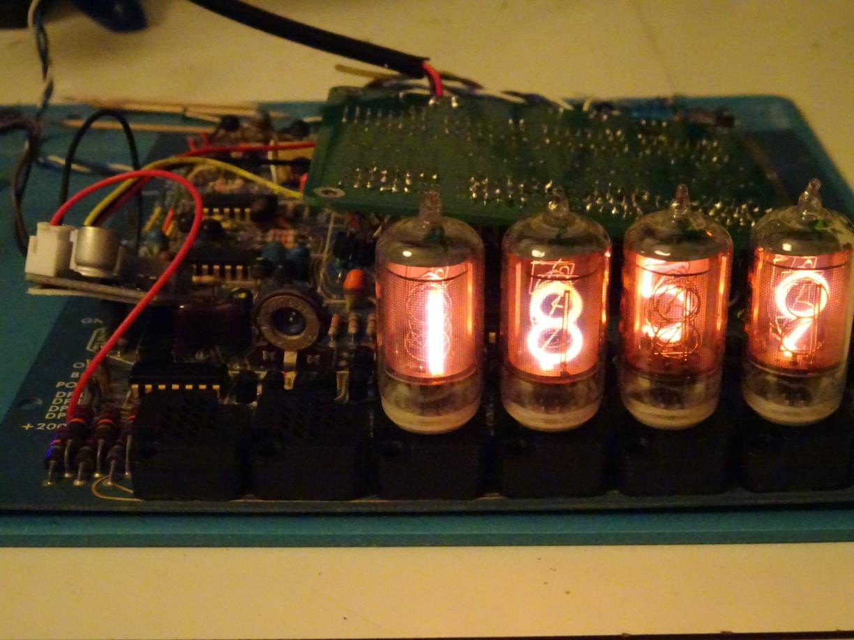
I plugged the nixies in and they just worked. Must have been decades since the gas inside was ionised. The minutes digit had a bug where it simultaneously showed both 4 and 6, or 5 and 7. This was simply the result of solder bridge between the 4/5 and 6/7 drive lines and readily fixed.
The result is in the headline photo. I'm chuffed. 🤗 And no, it's not a joke, I know what day today is. Good start to the weekend.
 Ken Yap
Discussions
Become a Hackaday.io Member
Create an account to leave a comment. Already have an account? Log In.