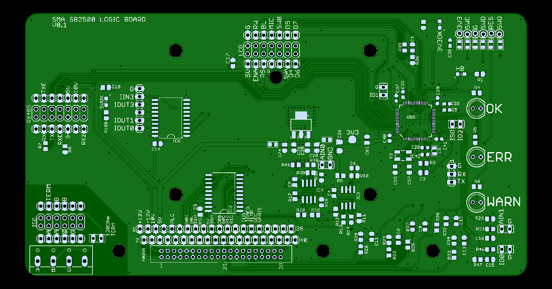
With the pinout figured out, a new PCB design can be made. It is quite a lot simpler than the old design. It uses an STM32F405 microcontroller. Which is much more powerful than the 16 bit processor used before. But I already had a complete power electronics software design for this processor.
The PCB does not contain much except for the microcontroller, some resistor dividers to go from 5v to 3.3 volt. Some opamps to go from -2.5 - 2.5 volt to 0-3.3v and some logic to voltage shift from 3.3 to 5v.
The PCB was kept flexible for when there would be pinout mistakes, and the extra pin headers next to all the main headers can be used for easy signal reading. The design can be found on Github.
The PCB is ordered at PCBWay, pictures will be shown in another log entry.

 ClimbinElectronics
Discussions
Become a Hackaday.io Member
Create an account to leave a comment. Already have an account? Log In.