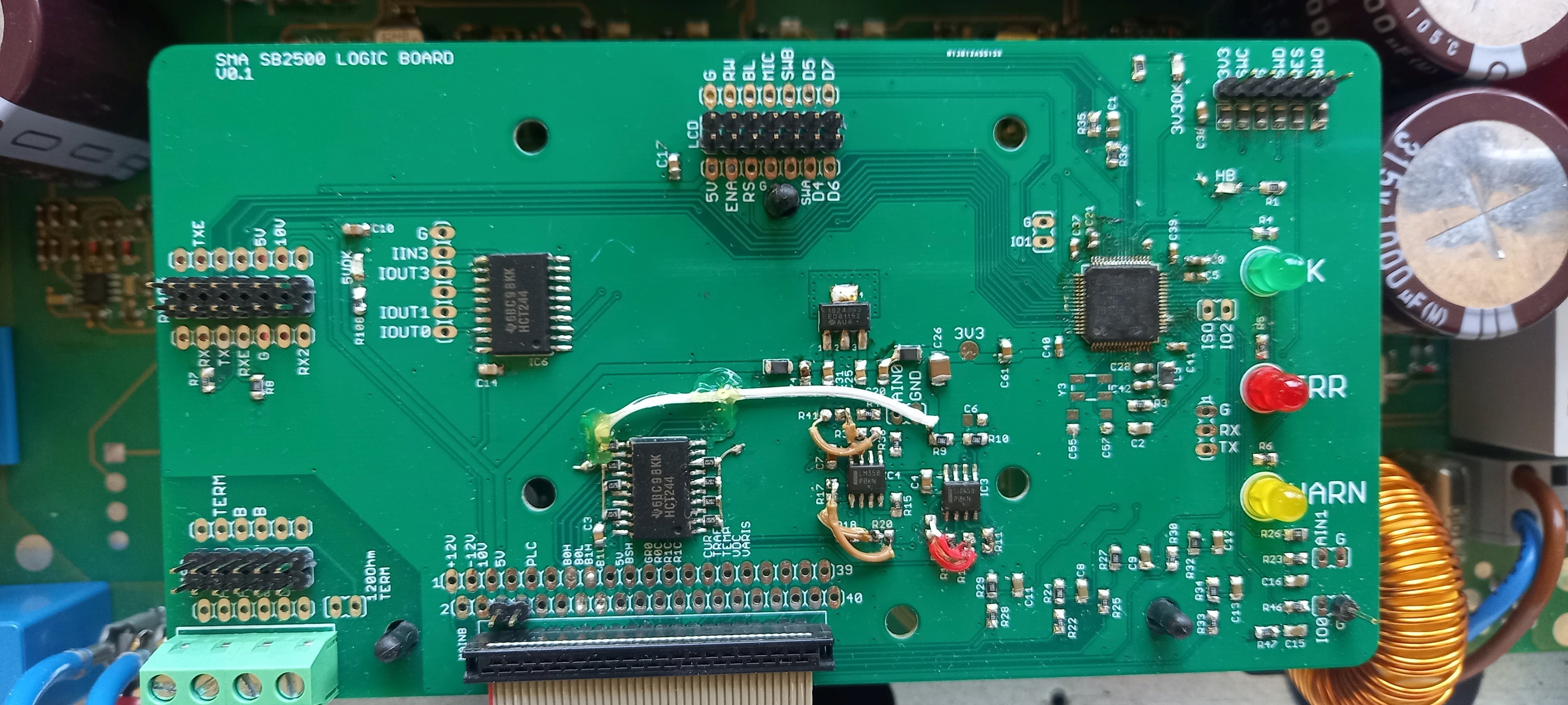
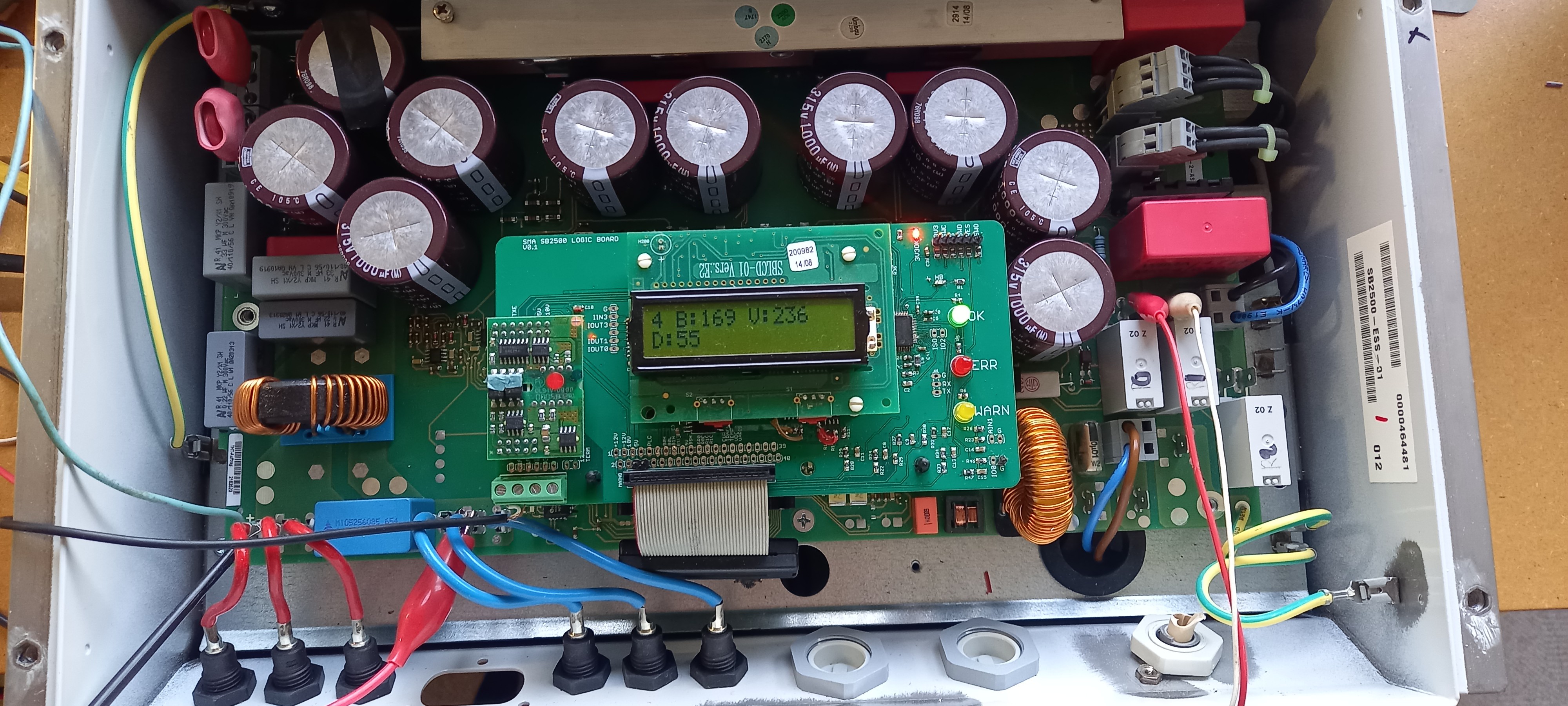
The PCB was received and soldered together. The opamp plus and minus inputs were reversed sadly, so some bodge wires were necessary. The status of the PWM outputs was undefined as long as the CPU was not started and the bridge shutdown was active high, so the H-bridge would directly short circuit the input stage when power was applied to the input. A few extra pull down and up resistors were added to fix this mistake. The PWM outputs were also in the wrong order due to a mismatch on the input and output of the 74HCT244 IC.
But after fixing all these mistakes, the board functions as it should.
After setting up all the hardware in STM32CubeMX, a hello world could be displayed and some LEDs started blinking.


 ClimbinElectronics
Discussions
Become a Hackaday.io Member
Create an account to leave a comment. Already have an account? Log In.