It seems that many of my projects these days are jump-started by ancient blog posts. Shoutout to Michael Ciuffo (aka ch00f) for figuring out the cartridge pinout and general usage way back in 2013.
How does it work?
- HitClips reproduce audio via two PWM outputs, each representing ½ of the original signal. When the signal goes “positive” (if we’re thinking in AC terms, voltage > 0), the magnitude is approximated via PWM on one pin, and when the signal goes “negative”, the first pin goes silent and the other pin spits out the PWM. The pin that is not actively PWM’ing should be pulled high (ch00f theorizes that it was set up this way “to directly drive the push and pull FETs of a class D amplifier“ in the player).
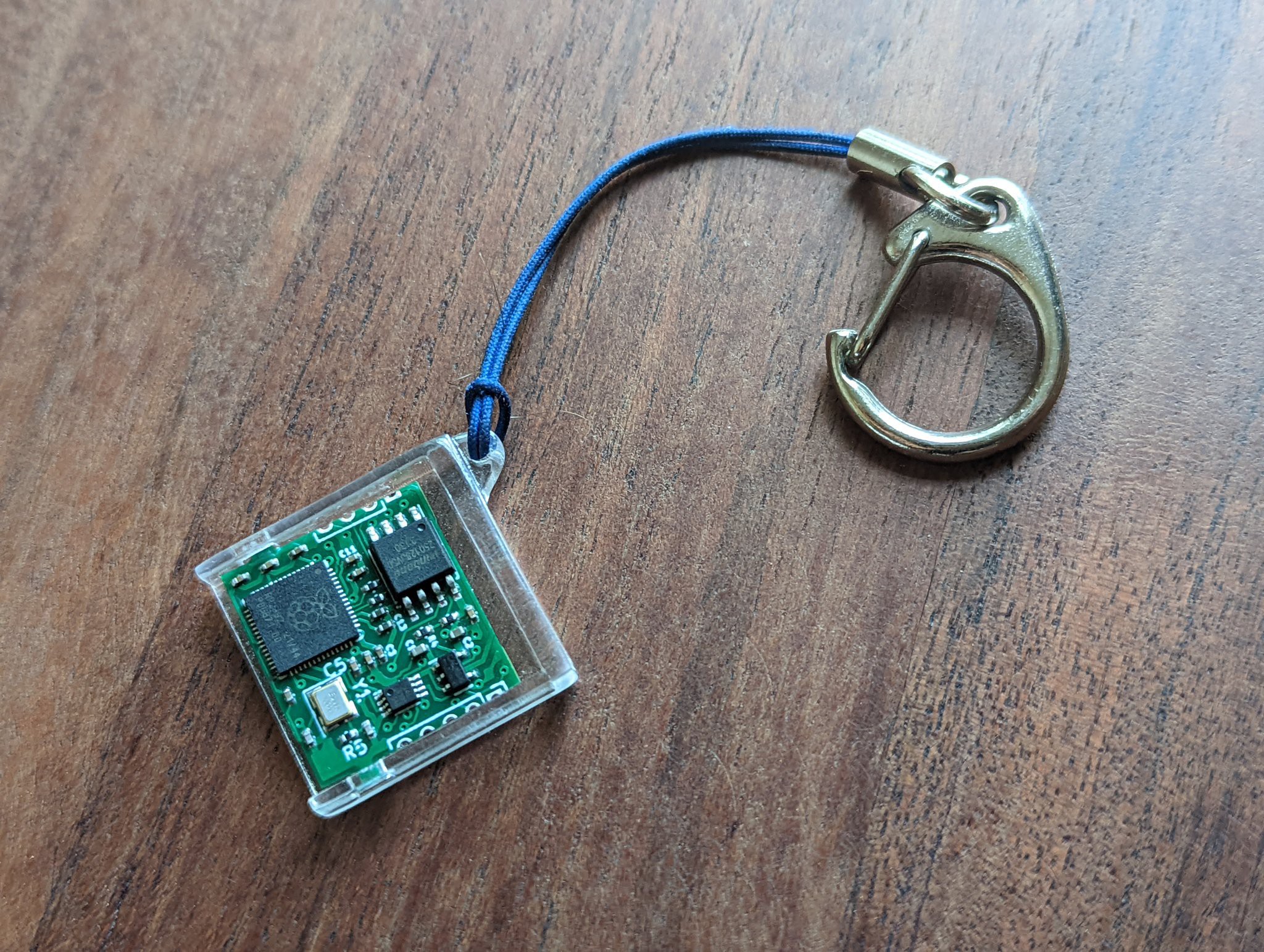
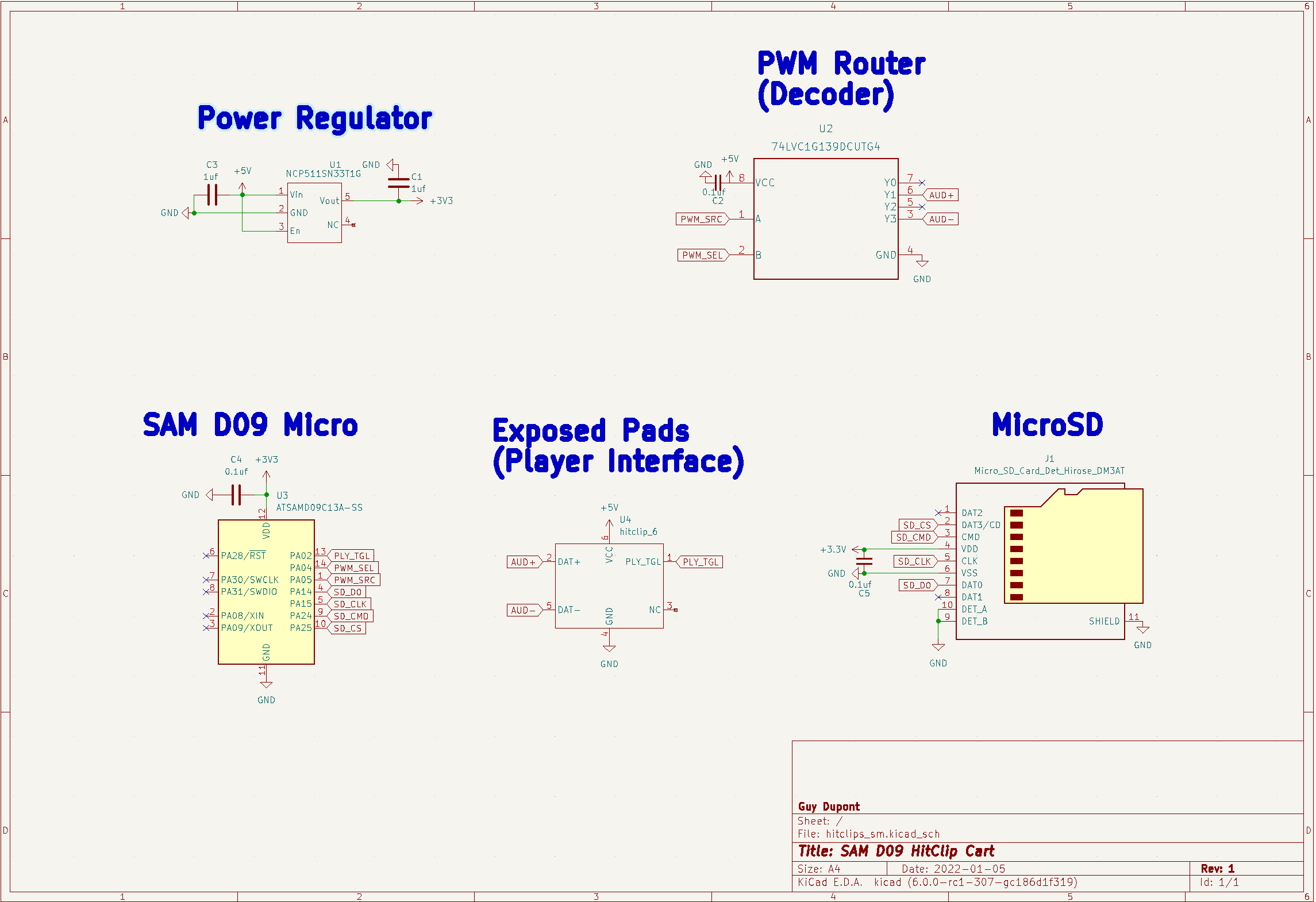
- My cartridge holds a SAM D09 microcontroller, which reads chunks of a PCM/WAV audio file from an onboard SD card and iteratively outputs each sample via the dual-pin PWM method described above (at a predefined interval, roughly 16khz).
- The player instructs the cartridge to stop/start playback by pulling pin [x] low via an external button. My firmware just naively monitors the state of this pin and restarts it’s main loop when it detects a transition from high to low.
Implementation notes:
- The players operate at ~4.5 volts DC, generally provided by (3) 1.5v batteries. This power is forwarded via spring fingers, which make contact with exposed pads on the cartridge. I am using a small linear regulator on my cartridge to knock this down to 3.3v for the microcontroller and SD card.
- I’m using the petitfs library for reading from the SD card. It uses bit-banged SPI, so all you have to do is drop a few C files into your project and provide macros for reading/setting the SPI pins high or low. Wonderfully portable! I should know, because the SAM D09 board was not the first one I chose…
- … I initially had this project running on an ATTINY84. However, with the slower internal clock (8Mhz vs 48Mhz) and smaller RAM (0.5kb vs 4kb), I couldn’t buffer enough audio during read cycles to keep up with the play “head” - at least not at an acceptable fidelity. Thankfully Timon pointed me towards the SAMD09 chips, which have the same footprint/external component requirements.
- I honestly could not figure out how to rapidly switch the PWM signal between two microcontroller pins (I am new to the SAMD world and I find the mux stuff very confusing). Instead, I am using a single pin for PWM and another GPIO pin to flag whether or not the signal should be “positive” or “negative” at any given moment. I then use an external “decoder” IC to route the PWM based on the state of the GPIO flag. As a bonus, the decoder chip is more flexible in terms of power input, so I am also using it to bump the PWM voltage back up to match the player’s. Is it still called “logic-level conversion” if it’s PWM? :shrug:
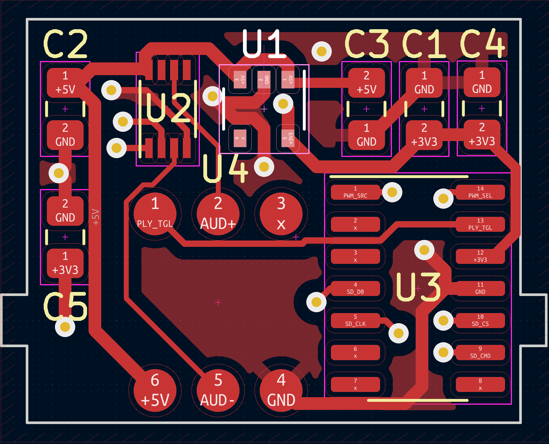
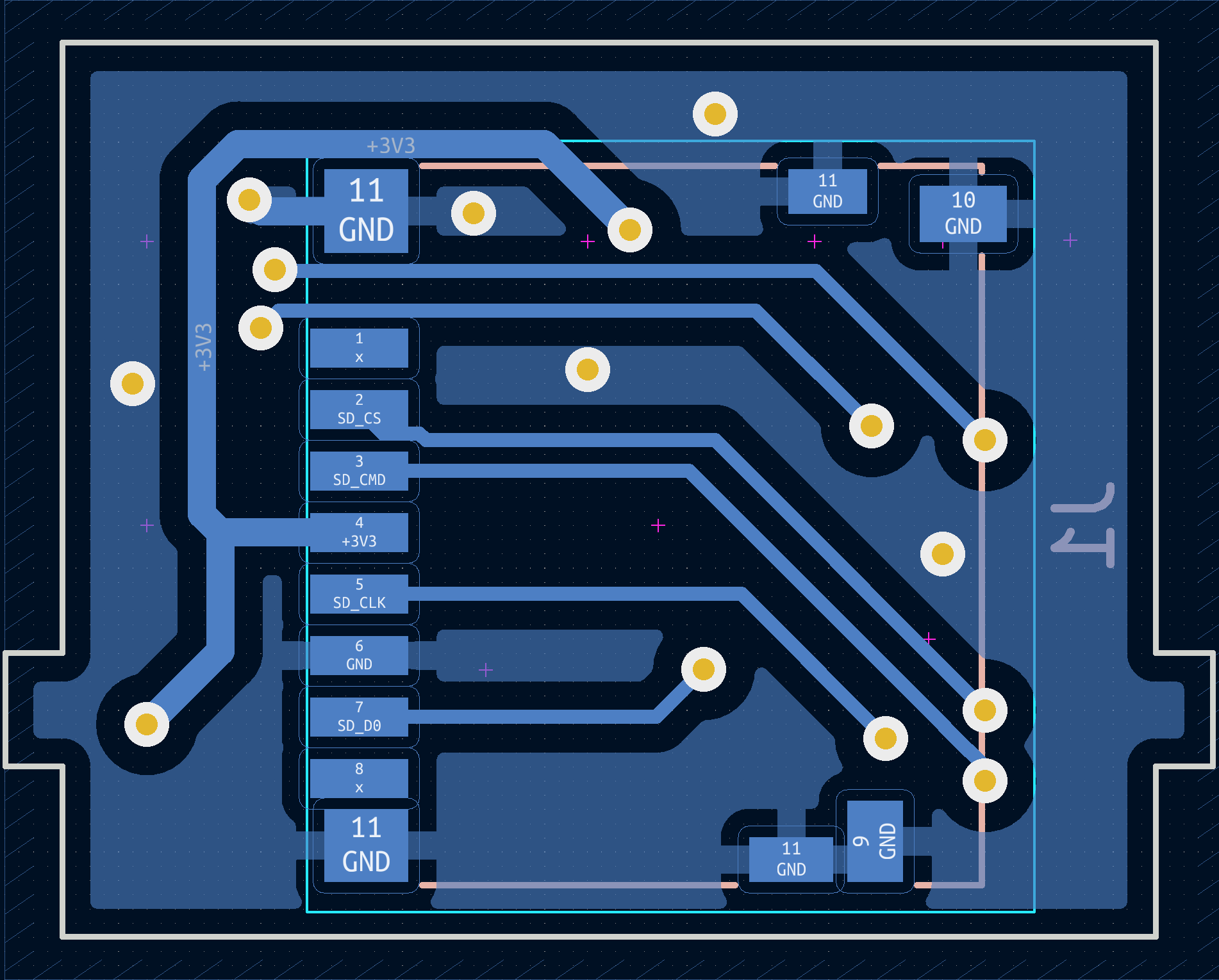
- I created a small “daughterboard” to stack on top of my main PCB, which makes the pads easier to reach by the player’s internal spring fingers and protects the surface mount components from potential snags. I initially planned to use small brass pins to connect the two boards, but eventually realized it was easier to just cover the pads on the original PCB with some big ol’ solder blobs, lay the daughterboard on top, and hit each external pad with a little heat/extra solder. This solution feels a little clunky, but ultimately paid off because I was able to quickly iterate on some alignment issues.
- You’ll notice my cartridges only have 6 pads, while the originals tend to have 8. I have no idea what the others are for! They aren’t connected on any of my cartridges, as far as I can tell. There are some fancy cartridges with extended functionality (like FM radio!), so maybe there’s something there.
 Guy Dupont


 mmueller-kaffeeschluerfercom
 typecad
 Steph
Steph
 Ayu
Ayu
Very interesting any closer to selling them yet I would love one of these