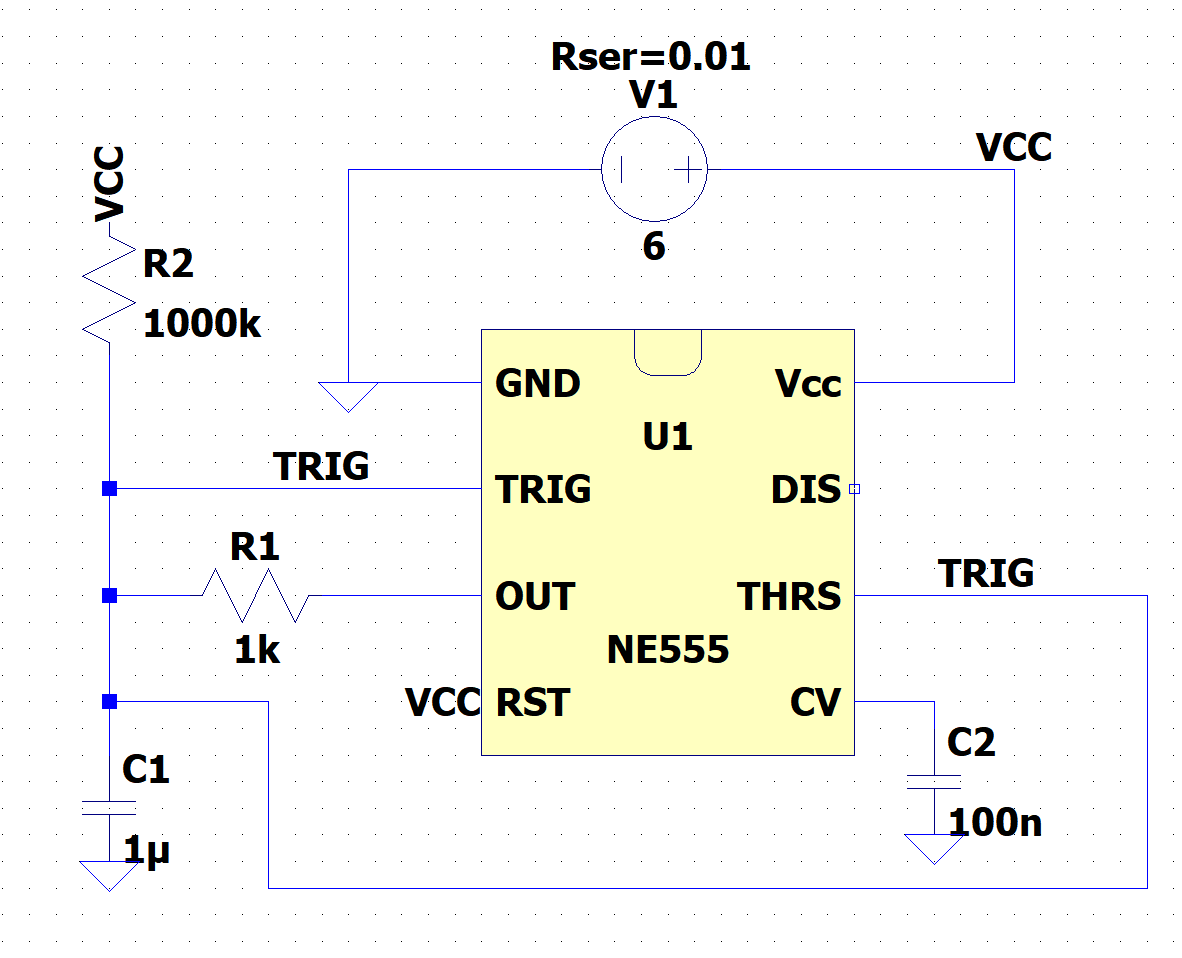
Clock A will be an astable 555 configured for 700Hz. We can achieve near 50% duty cycle using the configuration shown below. By introducing feedback between the output and C1, the capacitor charge and discharge is primarily controlled by R1. Charging will also be slightly helped out by R2, but if this value is large enough it should be negligible. [f ~ 1/(0.693*2*R1*C1) ]

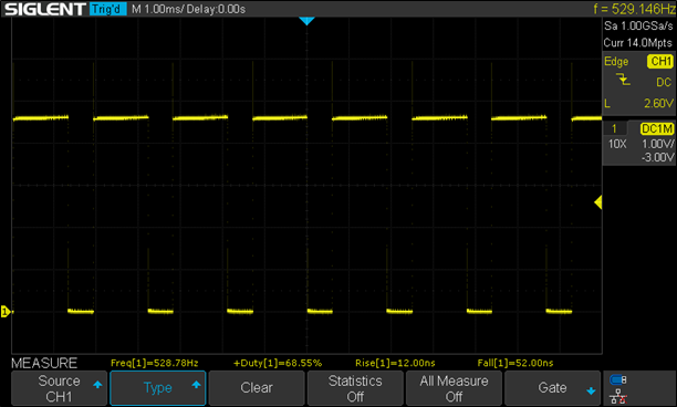
And here are the breadboarded results. Not perfect but the values can be tweaked pretty easily.

 Jesse Farrell
Discussions
Become a Hackaday.io Member
Create an account to leave a comment. Already have an account? Log In.