 Jesse Farrell
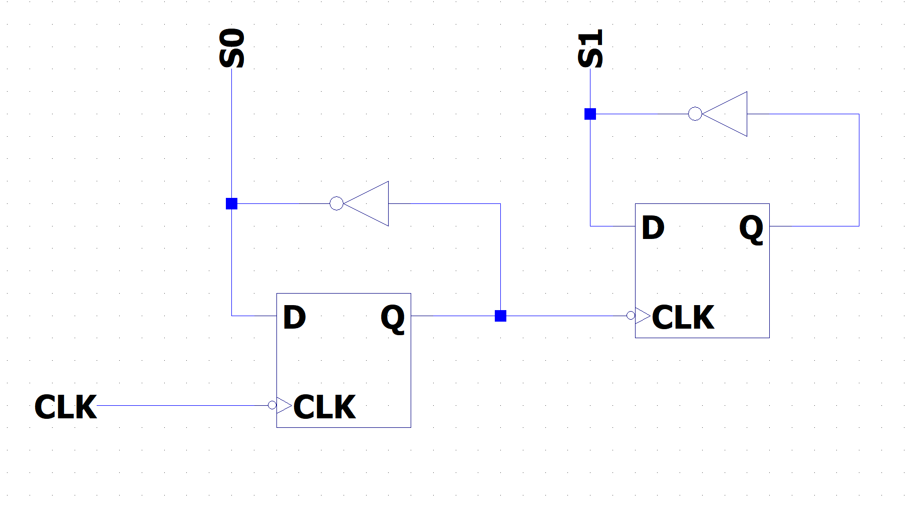
The “selector” circuit cycles through the different lines of the MUX. It would be very simple to implement this as two astable multivibrators, but over time the signals would likely drift apart. To get around this the selector circuit will be implemented as a frequency divider, seen below. This circuit works because the flip flop only toggle on the falling edge of the clock.
Discussions
Become a Hackaday.io Member
Create an account to leave a comment. Already have an account? Log In.