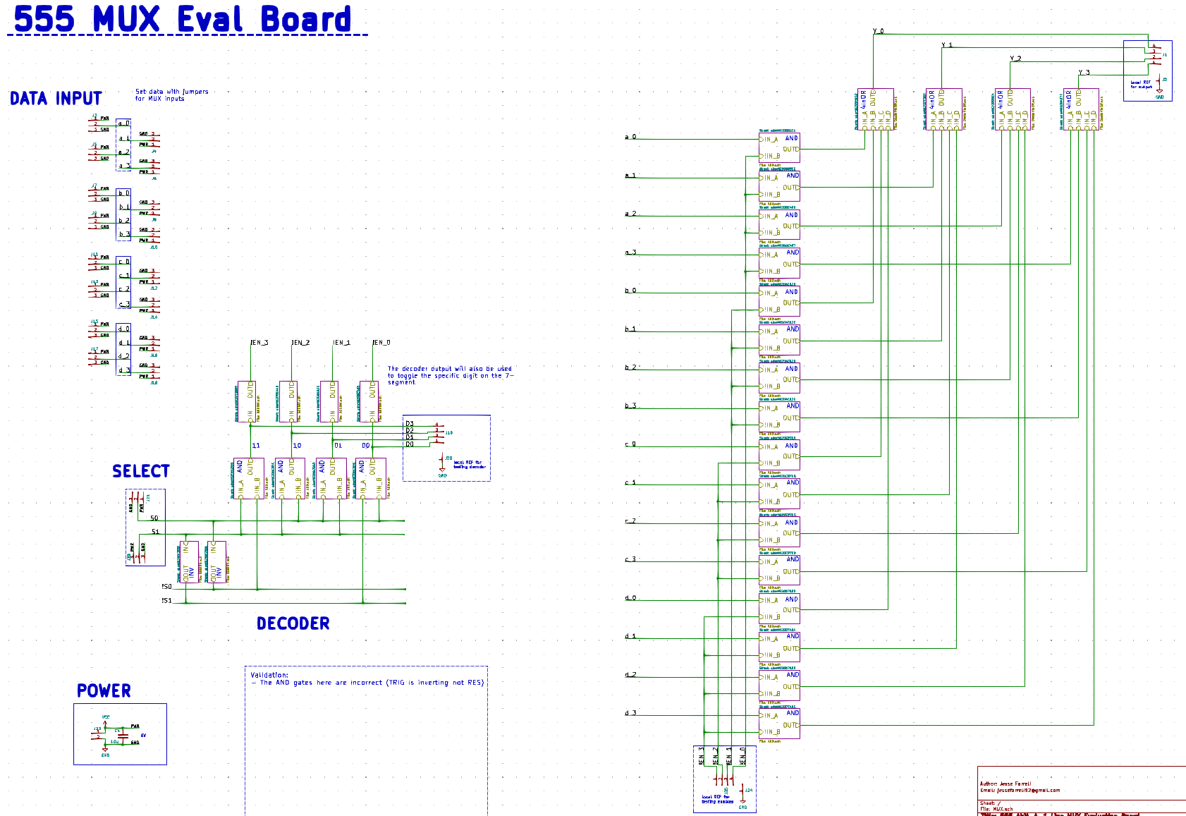
The 555 MUX schematic and pcb are shown below.


I managed to flip the inverting and none-inverting inputs of all the 555 AND gates of this circuit. Luckily, this circuit is simple enough, so I’m not very concerned about its validation. I was still able to confirm its basic functionality even with the aformentioned pin mixup. One thing I was curious about was its propagation delay.
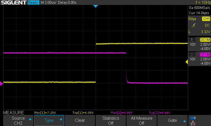
Overall, my MUX and BCD-7 Segment decoder need to be able to update within the period of the refresh clock signal (expecting to use 700Hz, so 1.4ms overall propagation delay is tolerable). The worst case propogation delay for this mux is theoretically ~15us x 5 = 75us (based on perivous validation). The observed delay was only ~5us.

I also tested the circuit with a 10k pull down (originally 2.2k) to see if I could reduce the forward voltage of the diode. This decreased the forward voltage by about 100mV (see images below), so not particularly noteworthy. However, increasing to 10k also increased the discharge of the diode diffusion capacitance seen on the right image below. I will keep using the 2.2k here for the final design.

 Jesse Farrell
Discussions
Become a Hackaday.io Member
Create an account to leave a comment. Already have an account? Log In.