 Sergio Ghirardelli
Max8815 board
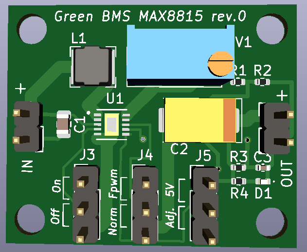
Max8815 board is Step-up converter based on MAX8815.
The project is designed according to MAX8815 data sheet:
https://datasheets.maximintegrated.com/en/ds/MAX8815A.pdf
The circuit has the following features:
Input: 1.5V - 5V
Output: 5V fixed or 3.3V - 5V (adjustable).
The max output current depends on input voltage. the board goes into protection when the input current exceeds 1A
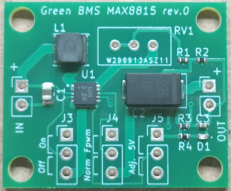
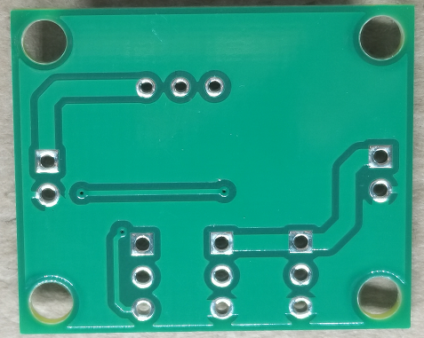
PCB production.
The board was made by PCBway.

I decided to order the pre-assembled PCB with the SMD components.
The result was excellent.
I greatly appreciated the assistance with continuous communication on the progress of the production.
Before shipping, they sent me photos of the product, to receive my "ok": this is very important!
Where to buy.
if you want to test this circuit, you can purchase the PCB pre-assembled with the smd components at the following link: https://www.pcbway.com/project/shareproject/MAX8815_step_up_converter_7f76c33b.html
It is possible to purchase only the PCB if you prefere
Instructions.
5V Fixed output:
- Set J3 shunt to "OFF" position
- Set J4 shunt to "Normal" position
- Set J5 shunt to "5v" position
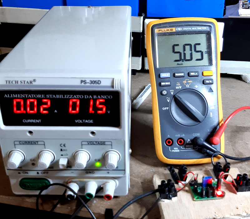
- Connect Input power supply (range 1,5v - 5v)
- Set J3 shunt to "ON" position
- Check D1 led lights ON
- Connect the output load
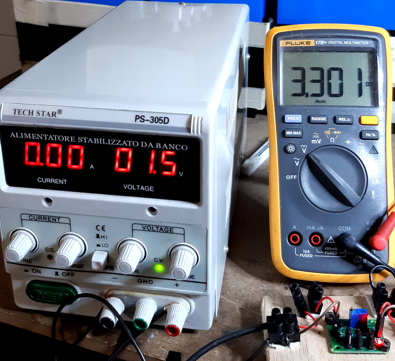
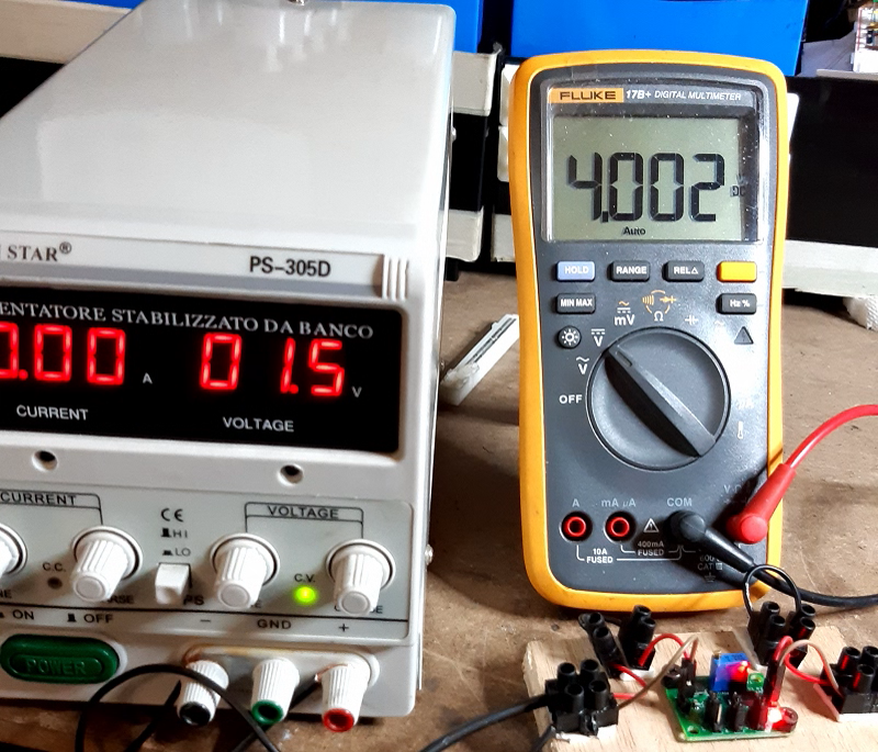
Adjustable output:
- Set J3 shunt to "OFF" position
- Set J4 shunt to "Normal" position
- Set J5 shunt to "Adj" position
- Connect Input power supply (range 1,5v - 5v)
- Set J3 shunt to "ON" position
- Check D1 led lights ON
- Set the output voltage (from 3,3v to 5v) by RV1 potentiometer
Other settings:
By J4 shunt it is possible to set "FPWM" mode according to MAX8815 data sheet
Opensource development application.
The project was created using Kicad

Opensource Hardware certification.
Max8815 board has been certified as open source hardware by the Open Source Hardware Association, with the UID: IT000008.
License.
This work is licensed under a Creative Commons Attribution-ShareAlike 4.0 International License. https://creativecommons.org/licenses/by-sa/4.0/
