 Jan Waclawek
The circuit to display minutes is cascaded to the seconds stage (which effectively provides a 1-pulse-per-minute output, 1PPM), and based on the same principle - it should charge the capacitor while ignoring the first 59 1PPM pulses, and reset itself upon the 60th pulse.
There are differences, though:
- parts used in the charging RC in the seconds stage were rather at the edge, as was the resulting current into capacitor. Here, we need 60x longer RC, so we need some trick, possibly increasing capacitance 60-fold, without the associated increase in parts cost.
- we don't need free-running oscillator operation, as the seconds stage provides free-running timebase (albeit inprecise) for the case of GPS not outputting the 1PPS signal (which GPS modules tend to do when they don't have a lock). All we need here is that for the first 59 seconds the output is low, and then it goes high. Also, a 1-minute "runback" of the indicator asociated with free-running discharge wouldn't be nice.
- the output from the seconds stage (which we take from the pin 3 (inverted), so that we have 1PPM for both synchronized and free-running seconds stage) may be as short as 100ms (or somewhat shorter, if the "synchronous discharge" resistor in the seconds stage is adjusted not entirely correctly); the "synchronous discharge" circuit in minutes stage has to take this into account.
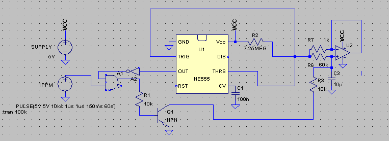
The first issue can be solved using an opamp-based "capacitance multiplier". In the linked circuit, choosing R2=R3=1kOhm and N=60 allows to use the same 10uF capacitor, while the entire circuit presents to its input an equivalent of R3=1kOhm and C=600uF. The 1kOhm value is negligible compared to the charging resistor of several MOhms.
The second issue is solved simply by disconnecting the discharge output (pin 7) from the capacitor.
The third issue is solved by connecting the "synchronous discharge" circuit not to the "virtual - multiplied" capacitor, but directly to the real capacitor itself. The discharging resistor is adjusted so that the discharge happens below 100ms, but slowly enough so that the 555 can cut off the discharge process as soon as the capacitor's voltage drops below 1/3 VCC. This is the modified circuit:
and following are the simulated waveforms (green is voltage on the "virtual capacitor" i.e. on TRIG and THRS pins of 555, red is simulated 1PPM signal from seconds stage, blue is output of pin 3 of 555; note, that 1 hour is 3.6ks):
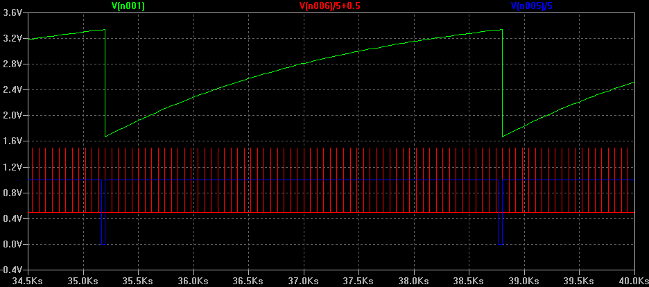
R2 has to be trimmed so, that nominal duration of 1 on output on pin 3 is 59.5 minutes, again, this provides tolerance for the cca 7500ppm temperature-induced error.
Charging C3 for a hour - rather than for a minute in the seconds stage - means 60x less current flowing into it, i.e. a few nA instead of 200-400nA. Isn't it a problem with the leakages of connected comparators/output circuitry then?
The problem is here slightly different: here, only leakage of the opamp applies directly to C3 (and also leakage of the "synchronous discharge" circuit, which has to be designed carefully in this regard). Charging current through R2 is still in the 200-400nA range, and it's the nature of the "capacitor multiplier" circuit, that most of the current from the "virtual capacitor's" input flows into the opamp's output, and only fraction of it into the real capacitor itself. So, the leakages on the "virtual capacitor" (i.e. leakages into TRIG and THRS, and also into opamp which will be added for the output to indicator) have to be compared to this 200-400nA current, thus are mostly negligible.
Discussions
Become a Hackaday.io Member
Create an account to leave a comment. Already have an account? Log In.