 Jan Waclawek
We have established that a 555-based timer is not precise enough as a timebase for a clock. So, let's employ a readily available precise clock source: a GPS receiver. Most GPS modules provide a one-pulse-per-second (1PPS) output, usually with user-adjustable pulse width.
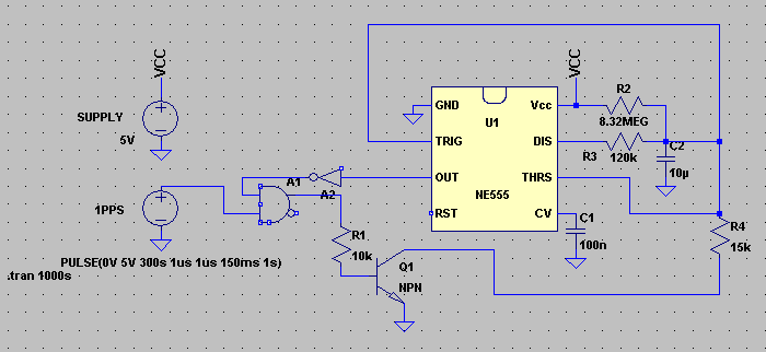
Now the challenge is to use this signal to discipline a 555, which will provide the signal driving the analog indicator (meter).
To indicate seconds, the 555 is to be used in the basic datasheet-given astable operation, where the resistors are chosen so that capacitor is charged through most of 60 seconds of a minute, and then relatively rapidly discharged. Voltage of the capacitor is amplified and output to the meter.
To utilize the 1PPS signal, the circuit has to reject somehow the first 59 pulses, and then use the 60th pulse to synchronize the astable process. So let's adjust the charging RC circuit so, that it charges the capacitor for 59 seconds, and then discharges it for 1 second. Visually, on the indicator, the 1s "runback" will be quite natural. Charging corresponds to the state when 555's output (pin 3) is 1 and discharging corresponds to output set to 0, so inverting this output and ANDing with the 1PPS signal provides the needed rejection of 59 pulses.
10uF PP capacitors are relatively affordable (they cost around $5) and 8MOhm resistors are still manageable. The charging current fluctuates between 200nA and 400nA, so as long as leakages are below the order of 200pA, this is a relatively safe arrangement. Of course, other leakages (PCB, soldering residua, etc.) have to be avoided, too.
Would this be not viable, the charging resistance would need to be decreased and capacity increased. Capacitance multiplier can be employed for this; we won't discuss it here as it will be utilized in the subsequent stages anyway.
The "unsynchronized" discharge through the 120k R3 provides the cca 1s discharge time. This provides both a free-running (although rather unprecise) timebase, and also a window to accept the 60th 1PPS pulse.
To keep things nice and slow, the "synchronized discharge" is set by R4 to last cca 100ms. The GPS module should be set so that the 1PPS pulse duration is somewhat longer, say 150ms.
To allow for the temperature-induced error, R2 has to be trimmed so, that the charging portion of waveform should last nominally cca 59.45s. This allows temperature-induced error of cca 450ms, or cca 7500ppm, which compared to 3000-4000ppm from our initial analysis allows for a bit more leeway for various sources of errors.
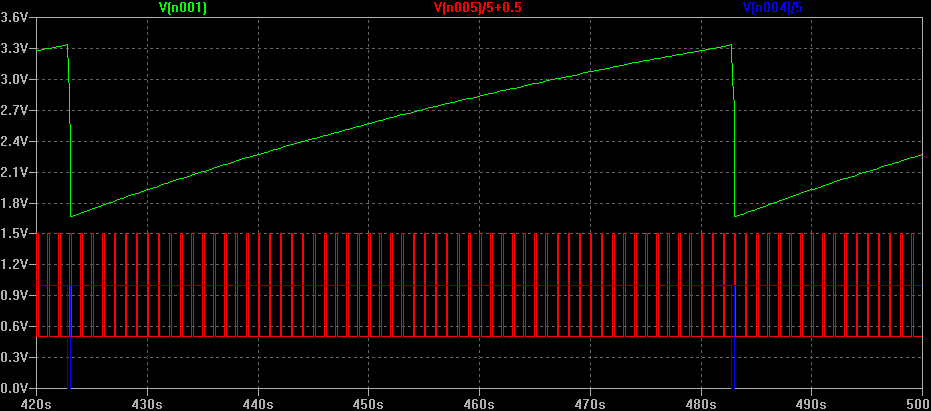
Below are the simulated waveforms of this circuit (green is voltage on capacitor, red is 1PPS (scaled and shifted), blue is output on pin 3 of 555 (scaled):
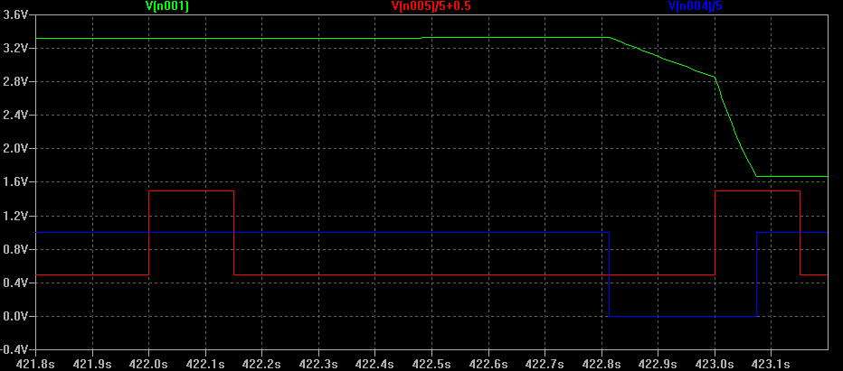
Below, the same waveform, zoomed, shows the slower "free running" in the first portion of discharge, cca 200ms (R2 in our simulation was not trimmed perfectly, otherwise we would see this portion to last cca 450ms) and the "synchronized" portion cca 80ms (again R4 is not set perfectly, but that won't really change much in the working of the circuit).
Discussions
Become a Hackaday.io Member
Create an account to leave a comment. Already have an account? Log In.