 Jan Waclawek
Voltage on the capacitor swings between 1/3 VCC and 2/3 VCC. To utilize the full swing of an analog meter, this needs to be amplified and shifted, so that the output waveform starts at zero. We need to use an amplifying stage which won't load the capacitor, anyway. Utilizing a JFET-input opamp (e.g. the venerable TL07x), the load is in the range of tens of pA, mostly negligible.
Following is an example shift-and-amplify circuit, resulting in full 0-VCC output swing:
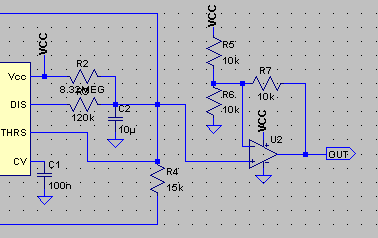
and the resulting waveforms (green is voltage on C2, blue is voltage on opamp's output):
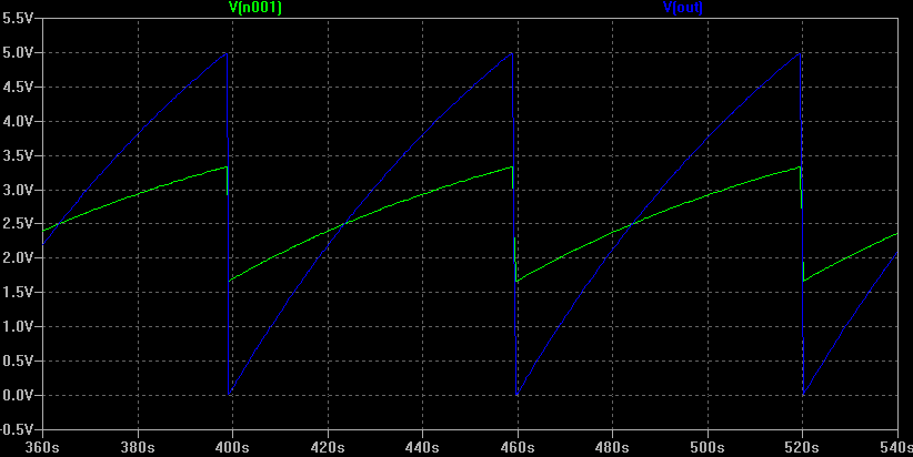
It is true that the rising portion of the waveform is not strictly linear, but this probably won't pose any problem - the difference is small, and the ticks/marks on the meters can be drawn with non-uniform spacing to match the true waveform.
Discussions
Become a Hackaday.io Member
Create an account to leave a comment. Already have an account? Log In.