 Jan Waclawek
Once the whole clock is up and running, there may be several things to tweak or at least think about.
The nonlinear nature of the output can be mitigated, if the simple charging resistor is replaced by a constant current source. A simple current mirror should suffice, to supply around 300nA into the capacitor.
The design, as it is now, results in continuous movement of the indicators. One could argue, that moving the indicators stepwise - i.e. making seconds/minutes/hours "jumps" - may be visually nicer. This again can be accomplished by further modifying the charging circuit, so that it delivers current in pulses. This might involve additional 555 for each stage in a monostable arrangement, to provide a well-timed pulse for each stage, however, the resulting complexity will significantly increase and the basic functionality may be harder to achieve. Also, in the hours stage, leakage might cause the indicator to move slowly downwards between the jumps.
In free-running mode (i.e. withouth 1PPS signal, when GPS module is out of lock) the current design of seconds stage results in nominally 59.45s+1s=60.45s period. This is around 7500ppm - given the inherent error is half that much, this is not entirely terrible, but not great either, and can be improved by a small trick. This lies in trimming the charging resistor R2 so, that in free-running mode it results in a nominal 60s period (consisting of 59s charging and 1s discharging); and adding a small circuit, which from the "synchronous reset" pulse pulls down pin 5 of 555 through a suitable resistor. Pin 5 is output from the 2/3 VCC point of the 3-resistor divider providing reference to the comparators, so by pulling it slightly down, the discharge cycle runs "deeper" than normally, resulting in a slightly longer charging cycle. The nominal values of the resistor divider depend on the 555 variant - the "classic" variant has a 5k/5k/5k "ladder", whereas the low-consumption CMOS variants tend to have cca 10-20x higher values; so the "tweaking" resistor has to be adjusted according to given 555 variant so, that in synchronous mode (or with the "tweaking" resistor forcibly pulled to ground) the charging part lasts nominally 59.45s.
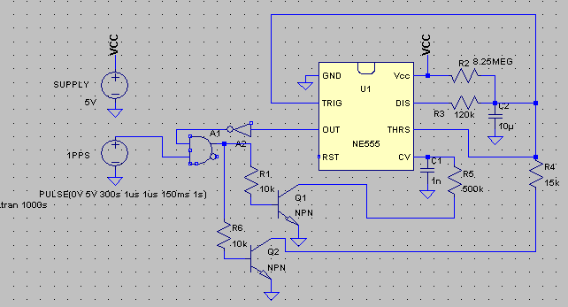
In this diagram, the "tweaking" circuit consists of Q1 and R5:
Below is comparison of free-running (top) and synchronous (bottom) modes (free-running charging duration is not adjusted to exactly 59.00s, as the discharge duration is slighly off, too). Cursors are set so, that in Diff Horz duration of charging can be seen, and Cursor1 Vert indicates the bottom of discharge, i.e. the nonshifted/shifted 1/3 VCC reference value (green is voltage on capacitor, blue is scaled output on pin 3):
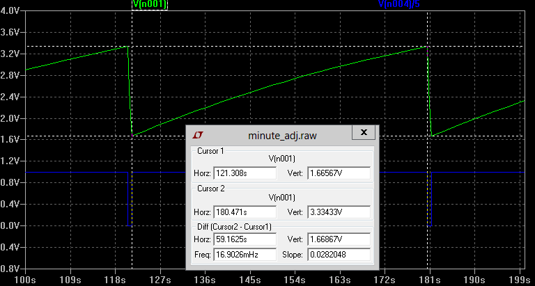
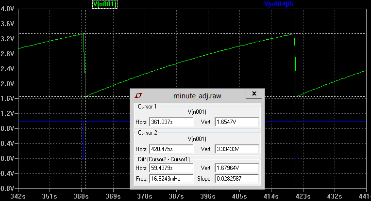
It takes cca 10mV change of the 1/3 VCC reference (i.e. 20mV shift at pin 5) to change the charging time by cca 300ms.
Discussions
Become a Hackaday.io Member
Create an account to leave a comment. Already have an account? Log In.