I got a piece of advice from my friends to always prototype schematics on breadboards. This is the way you can connect and reconnect everything, add or remove components, change controller pins and check everything with an oscillograph".
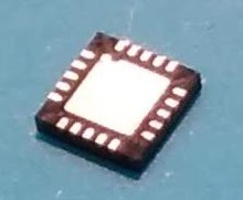
My controller is small. It's just a 4 mm square.
In order to connect it to a breadboard I needed a QFN-20 0.5mm adapter like this.
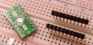
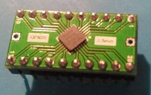
I easily found mine on eBay and if it is not the case for your footprint you can always create it as a separate PCB. So I soldered my controller to the adapter with soldering paste and a heat gun. And then I soldered the pins headers:
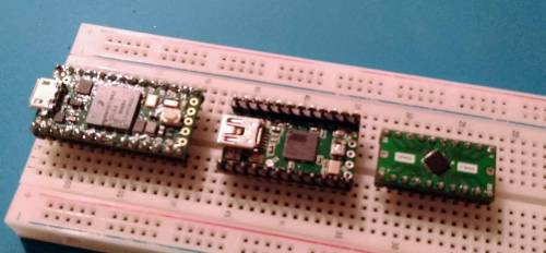
So this is all breakouts I have so far:
| Model | CPU | Speed MHz | RAM | Program Memory | USB | PINs | Price $ |
| Teensy 4.0 | ARM | 600 | 1Mb | 2Mb | micro | 40 | 20 |
| Teensy 2.0 | AVR | 16 | 2Kb | 32Kb | mini | 25 | 16 |
| Mine | AVR | 1 | 128 bytes | 2Kb | - | 17 | 2 |
I spent lots of time trying to make the Arduino-based programmer work with my microcontroller. I almost gave up but soon I found out that the factory ISP programmer is available and it's only $20. When I gave it a try, it connected to my controller in no time and made it work right at the bat.
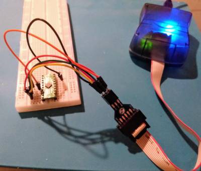
Then I replicated my schematics on two connected breadboards:
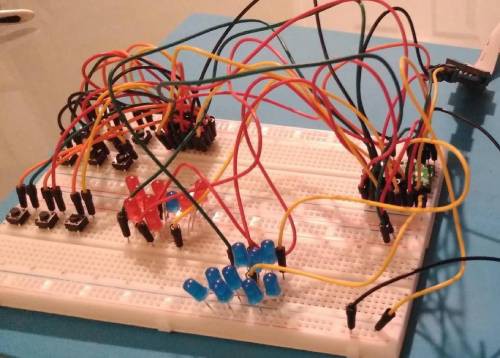
With the help of this mesh of wires and components I managed to write and debug my firmware that can be found here.
 Andrey Kalmatskiy
Discussions
Become a Hackaday.io Member
Create an account to leave a comment. Already have an account? Log In.