 Andrey Kalmatskiy
To solder using the generic heat gun, you need to set it to max power and min flow and remove all focusing attachments.
1. I applied solder paste (Next time I'll order a $8 stencil):
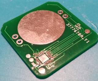
2. Then I aligned the controller.
3. I used a spare PCB and a multimeter thermometer to find a distance to my heat gun that makes it 250°C. I used my helping-hands aka third hand to hold the PCB horizontally at the measured distance and attached the thermometer.
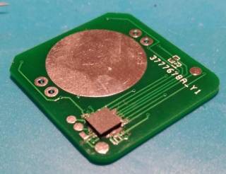
4. Then I exposed the PCB to heat checking the temperature: 150°C (15 sec) →250°C (5 sec)→cool-down. I applied to much paste, so I got a lot of bridges:
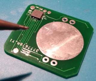
5. To fix that I generously applied flux and heat it up with my thinnest bevel soldering tip. Result is acceptable. No bridges.
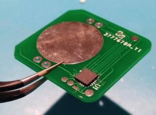
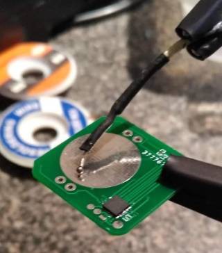
Then I soldered some temporary wires for power, reset and SPI and loaded a firmware (now I know that I should've added some M/F connectors or at least pogo pads).
Next is - other side soldering.
Discussions
Become a Hackaday.io Member
Create an account to leave a comment. Already have an account? Log In.