 Austin Allen
Introduction
This article is part of a series discussing methods for adding sensing capabilities to a DIY telescoping pole project made from EMT conduit.
Force sensing, in the context of a telescoping pole, refers to ability to measure the side/lateral load that is exerted at the tip of the pole. Having this capability can be useful for any kind of project where a DIY telescoping pole is needed:
- Birdfeeder - Know when the feeder has been visited by a bird, according to when the pole has flexed.
- Structural - A greenhouse, tent, or awning support can be monitored remotely, and give the user time to dismantle the structure and prevent collapse in inclement weather.
- Antenna - Again, inclement and windy weather can be detected so that the antenna can be lowered before damage occurs.
- Long-reach grabber/picker - Sense the weight of the object being carried by the tip of the pole.
- Volleyball net - Detect a "let serve", in which the volleyball serve has touched the net. This causes the net's supporting poles to flex, which can then be detected.
- Flagpole - If the pole is flexing often, that implies that the weather is windy/stormy, and that you may need to lower the flag to protect it.
This article will show you how to add force-sensing to an EMT conduit telescoping pole by utilizing low-cost, off-the-shelf components.
Disclosure: Some of the links in this article are affiliate links. This means that, at zero cost to you, I will earn an affiliate commission if you click through the link and finalize a purchase.
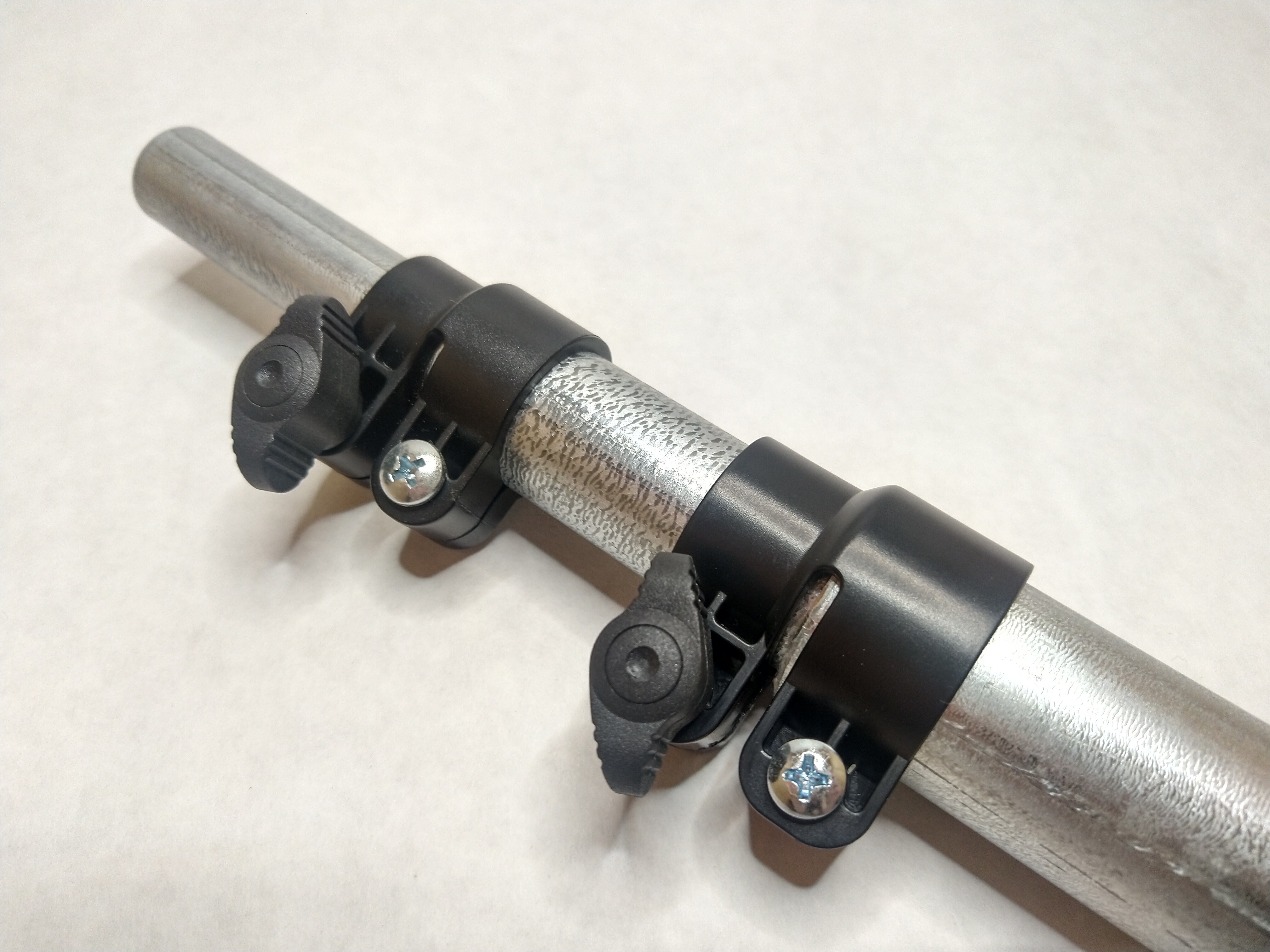
- EMT conduit telescoping coupling
- 1", 3/4", and 1/2" EMT conduit from your local hardware store
- Force-sensing strain gauges
- An Arduino microcontroller
- And some additional electronics!
Working Principle
Adding force sensing to a telescoping pole can be accomplished using one of several sensing methods - one such method utilizes so-called "strain gauges." The working principle for a strain gauge is the following:
- When a metal wire is stretched (i.e. mechanically strained), its electrical resistance decreases as explained here.
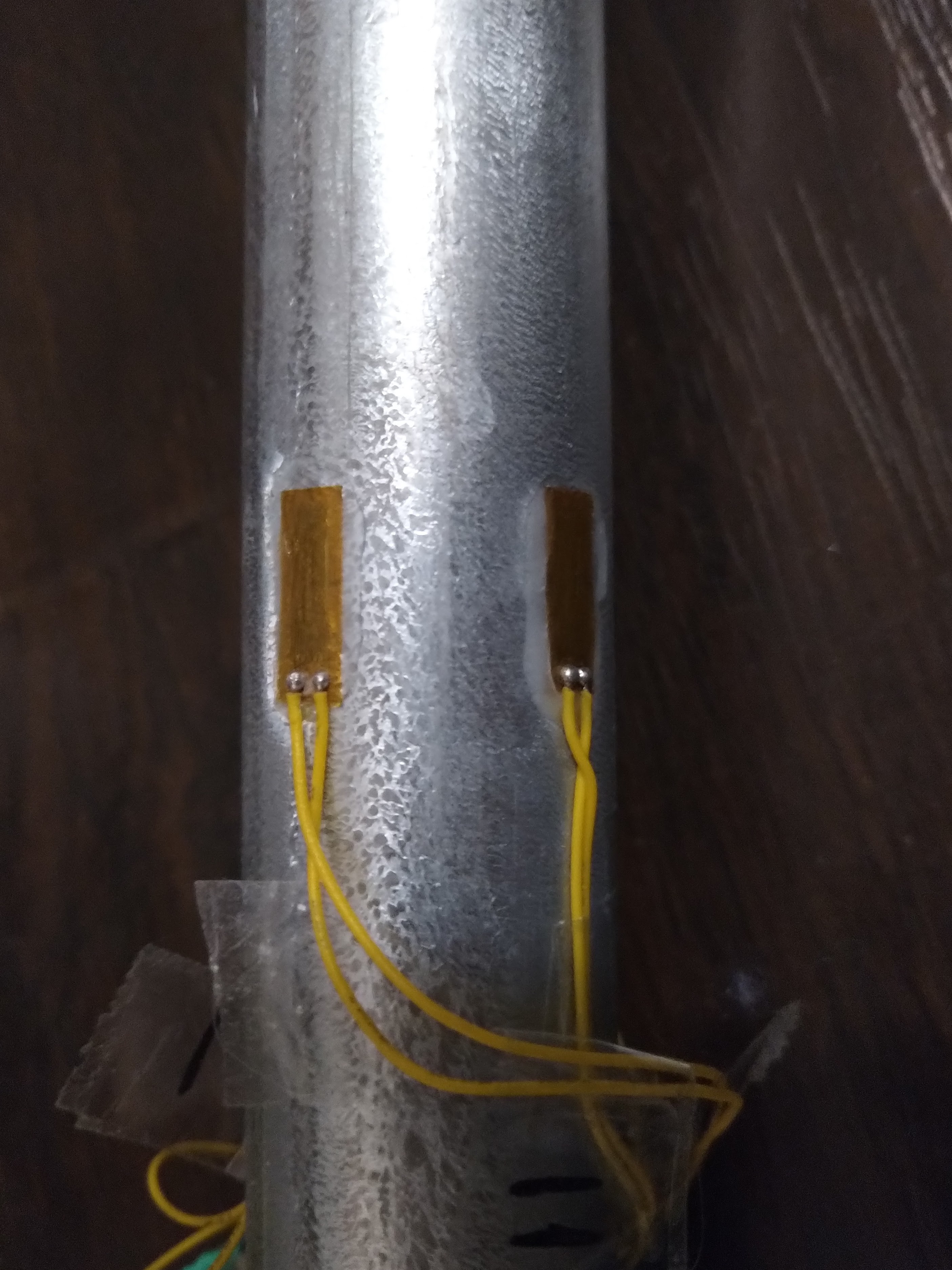
- A strain gauge makes use of this effect by using a small zig-zagging wire (trace) in a thin, flexible circuit board. This circuit board is glued to the outer surface of the object to be measured. When the object flexes, the circuit board flexes too.
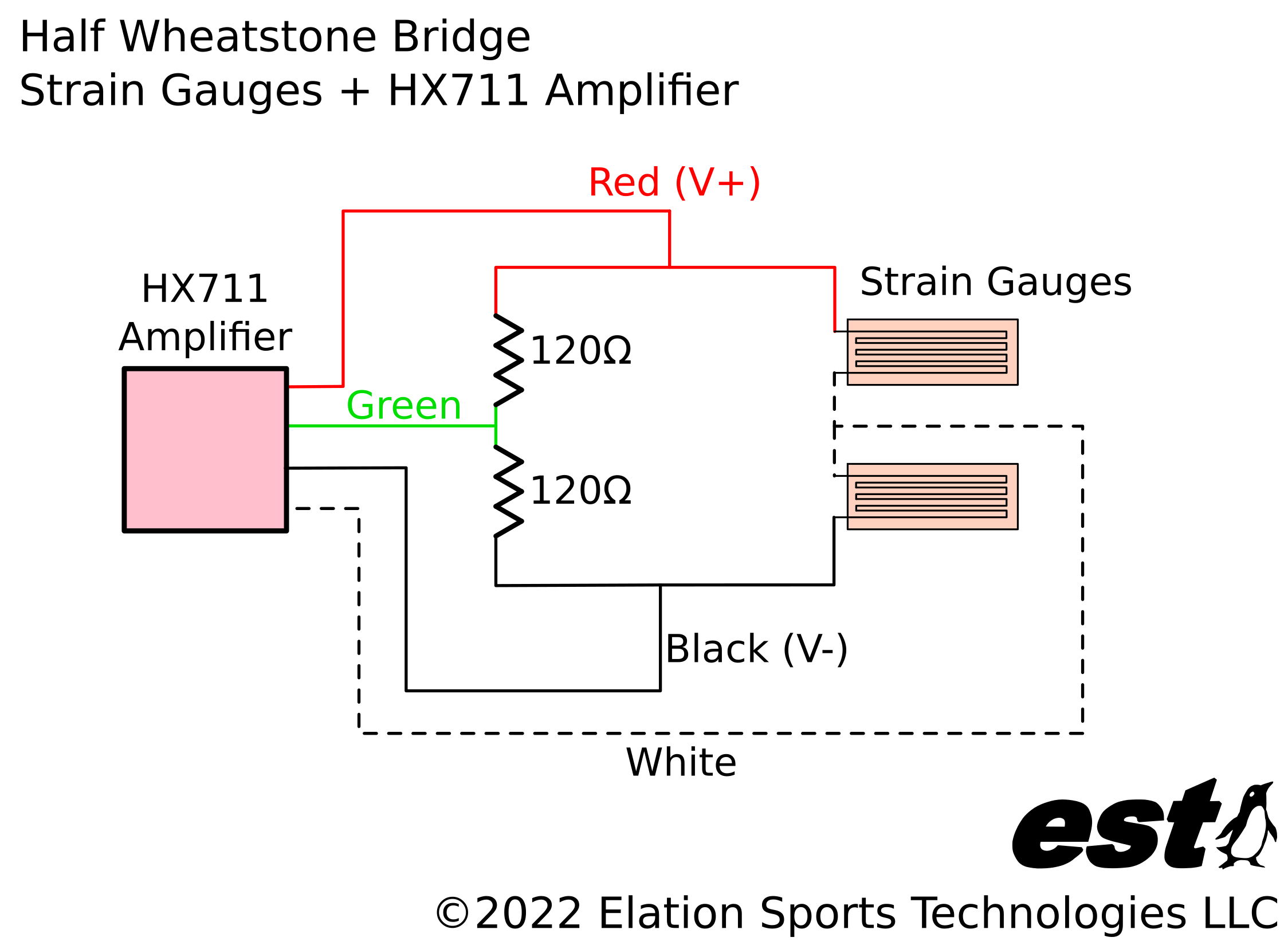
- The stretching of that circuit board changes its electrical resistance slightly, and that small resistance change is detected using a circuit that amplifies the change so it can be more easily detected (the wiring configuration for the strain gauge is called a Wheatstone bridge.)
- The resistance change correlates to the magnitude of the force/load that carried by the object - and so, the force applied to the measured object is known.
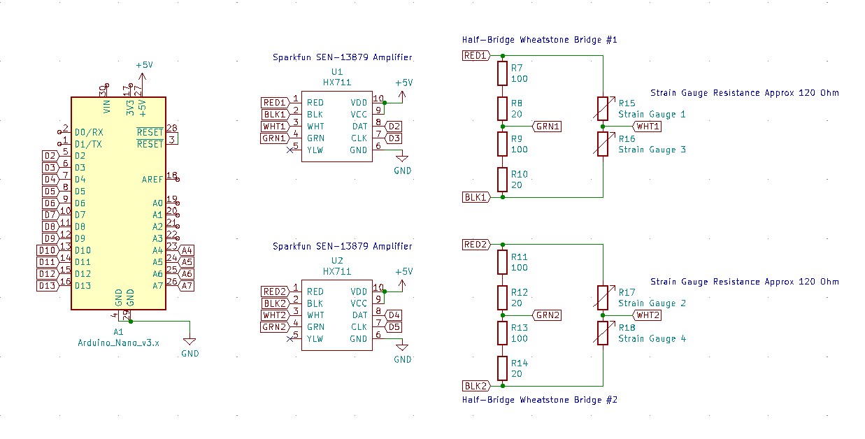
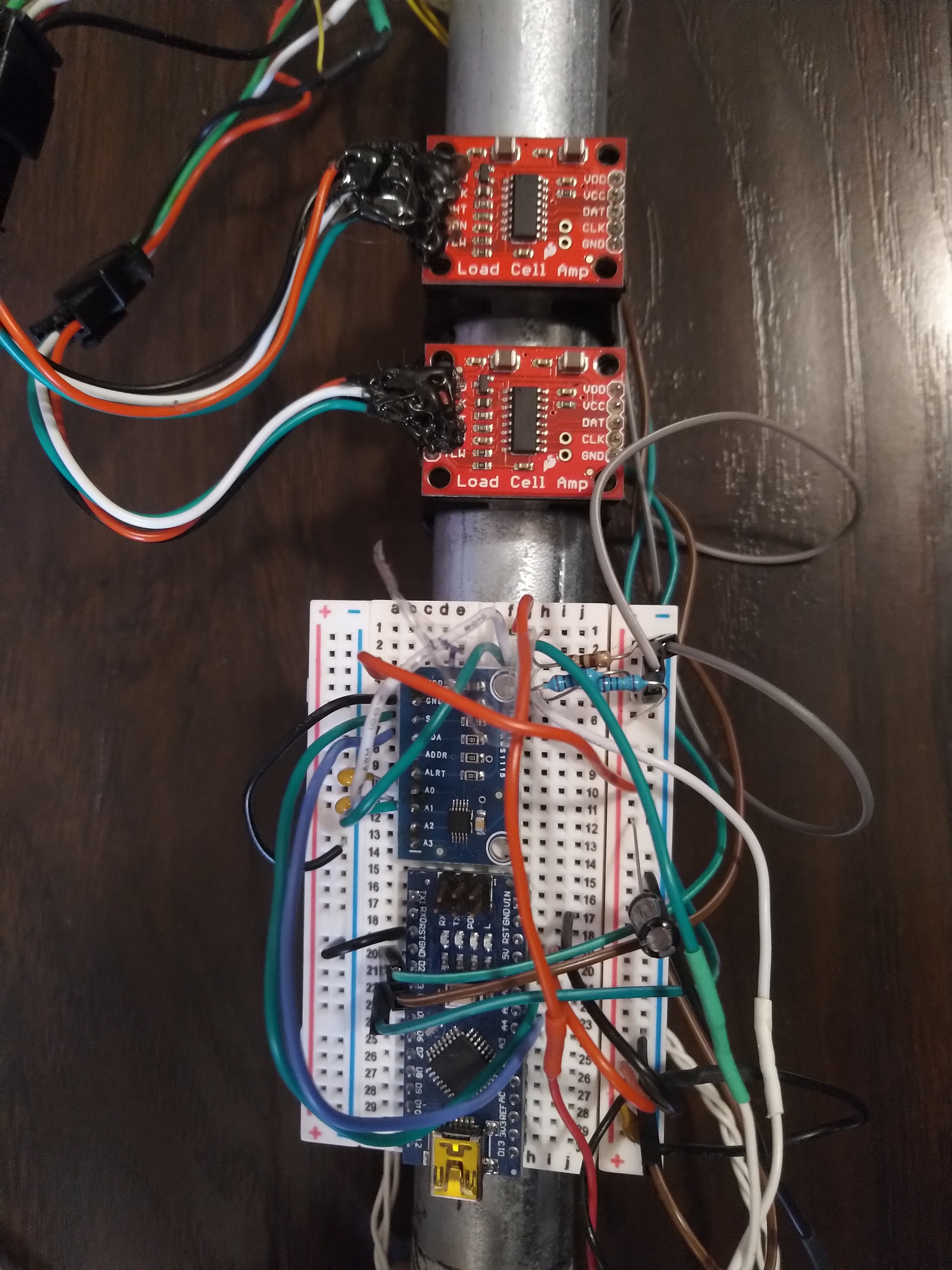
Strain gauges come in different shapes and sizes, and they can be used to detect bending, axial/lengthwise stretching, and torsion/twist. A "Wheatstone bridge" is the wiring configuration that is often used for using strain gauge sensors. In order to measure both the magnitude of the pole's tip force and its direction, we used two pairs of half-bridge Wheatstone bridges consisting of 2 x strain gauges and 2 x 120Ω resistors per circuit. Each circuit is connected to a Sparkfun HX711 SEN-13879 amplifier, and an Arduino Nano microcontroller is used to record the force measurements from the pole. The flow of data is visualized below:
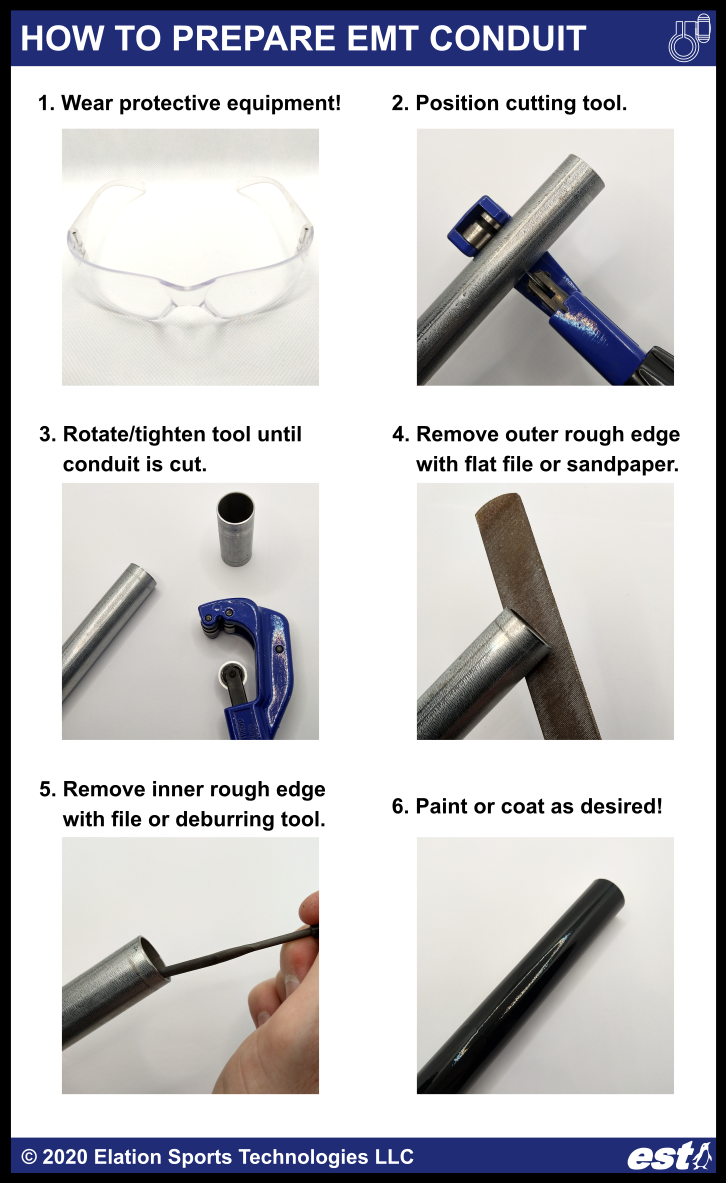 Assemble your telescoping pole - creating a telescoping pole from EMT conduit is easy using the
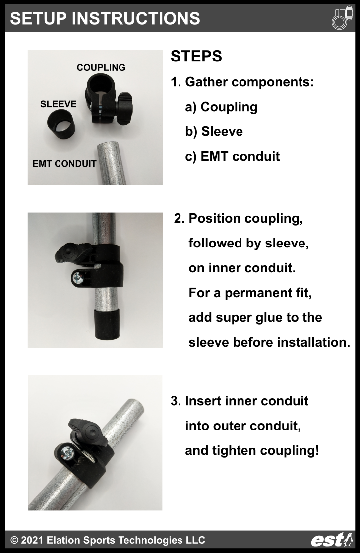
 RachelAnne
 will.stevens
 MaBe42
 artbyphysicistkitty