 Jesse Farrell
To get started I wanted to understand what I’m working with. If I just toggle the pin, I’m able to get ~50ns pulse widths. This makes sense since our clock is 20MHz = 50ns period.
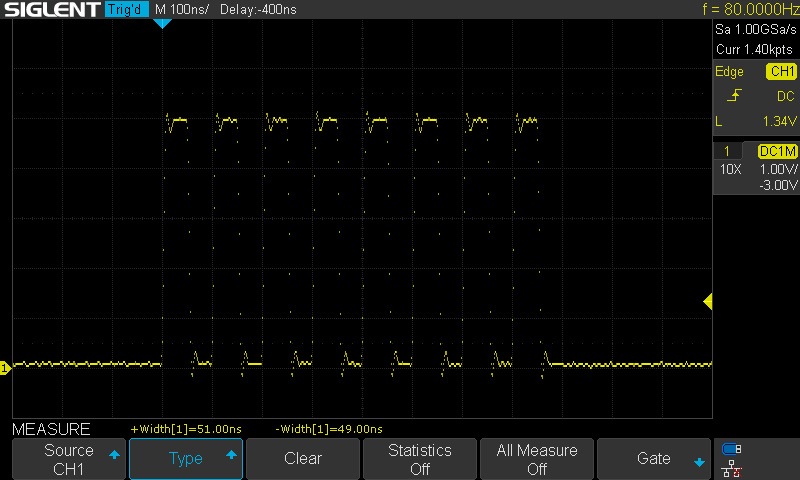
To extend the pulse widths I'll insert _asm(“nop”) commands. This is an assembly command telling the MCU to perform no operation. Assuming this instruction will only take 1 clock cycle (seems like pretty good assumption), I will need to pad the output toggle with around 7/8, and 15/16 to achieve the timings in the table below.
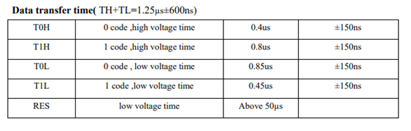
Here’s a hardcoded 0 using "nop" to configure the timings. The _asm(“nop”) instruction works as expected, and although it’s a bit wasteful its pretty handy.
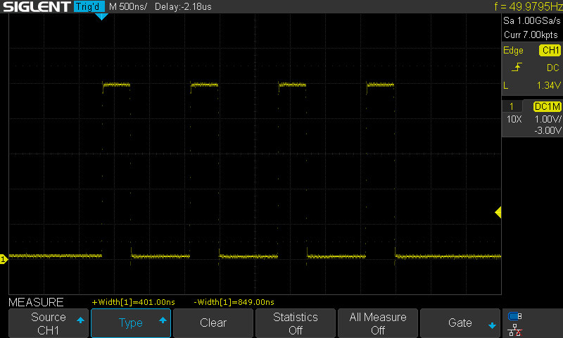
I moved the hardcoded 1/0 code into a function and called this function 24x to test a single WS2812B. With a bit of tweaking to account for delays entering and exiting the functions, the IC worked as expected. Here's a couple pictures of the different colors on the lowest brightness.
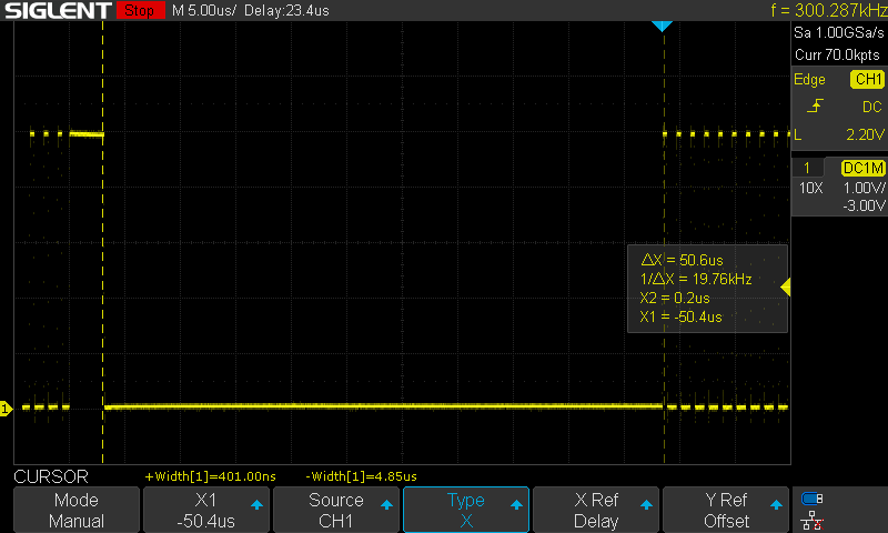
Testing the reset command, it looks like the IC follows its spec closely. It won’t reset below a 50us hold time. In this capture the signal was held low for approximately 50us but the LED did not update (cursors were likely a bit offset here). Increasing the delay to 55us and the IC worked as expected.
Discussions
Become a Hackaday.io Member
Create an account to leave a comment. Already have an account? Log In.