 alcor6502
Some history
At the origin of the horizontal blade flip technology clock, patented in 1958 by Solari & C, sits the "Cifra 5". This clock was the first of a family of industrial timepieces developed from a technology studied by Remigio Solari, who revolutionized the usual methods of displaying time and information to the public
The clock consisted of four palettes of ten numbers to display the time in the military format "HH:MM." There were two types of this clock: the first one, called "master," had inside a whole electromechanical clock including a device capable of delivering a polarity alternate 24V pulse every minute. The second type, called "slave," can display the same time in sync using the alternating pulse coming from the master. This configuration was beneficial when used in train stations or airports where many clocks should display the time simultaneously through all the installed devices.
Since the slave clock's production outnumbered the master one, it's pretty common to find a used slave; many people consider it a simple decoration object since it can't keep time. When I saw this clock in an antique shop in Bologna, I quickly fell in love; the early 70's style was unique. After a lengthy negotiation with the shop owner, I walked away with this piece of history. The owner warned me the clock was a slave; without the master, it would never show the time. For me was like ice over the cake; not only I was a proud owner of an original Cifra 5, but also it would be the inspiration for a great hack. My intentions were quite ambitious. I wanted to modify the clock to be completely autonomous: when powered to self adjust to the current time and then keep time.
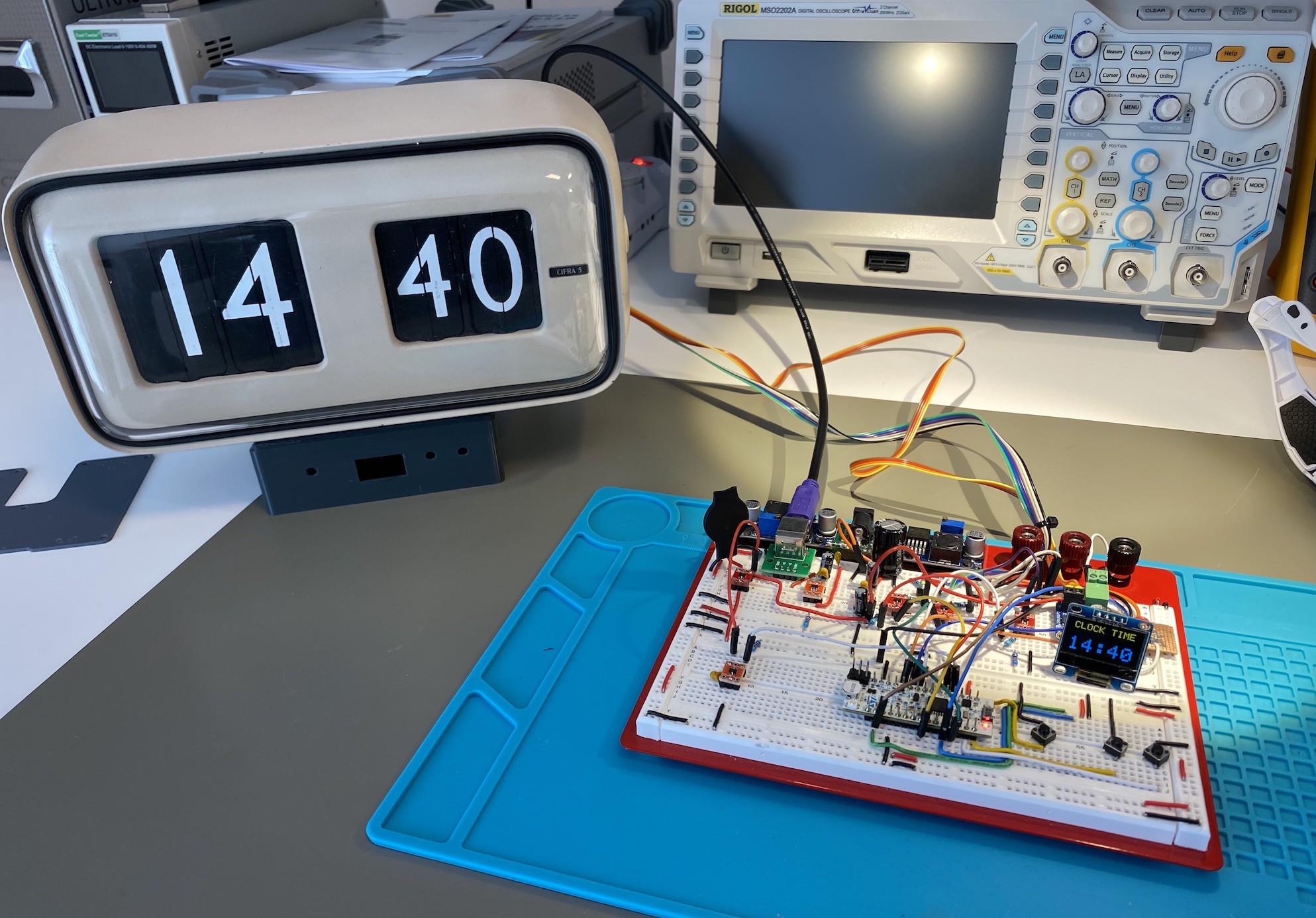
In the video below you can see the control board fully assembled and the internal actuator and sensors used to adjust the clock.
A fully automated modern clock
The slave version had many similarities with the master; the main difference, a massive coil was used to flip the single minute's palette; all other palette movements: like tens of minutes, hours, and tenth of hours, were generated by mechanical levers; just a flip polarity pulse every minute was necessary to make the clock fully functional. Some practical tests confirmed my analysis: the timekeeping was relatively trivial; just send an alternating pulse, and the clock will take care of everything.
On the other hand, setting the correct time as the initial adjustment wasn't a simple task. Further analysis revealed the control board needed two critical signals: one for the new hour mark and another for a midnight mark (when the clock shows 00:00). With these two signals at hand, it was simple to draft a basic algorithm to set the clock to any specific time.
It was imperative to not modify in any way the original mechanism, so harvesting those signals from the clock required some 3D printed parts to position two Hall sensors and two magnets.
For the new hour mark, it was tracked the movement of the lever that increments the hours by one. To simply test if the minute pulse has triggered a new hour, you just have to compare the previous read of the sensor and a new read after the pulse; if the status of the sensor has changed from Off to On, the minute's digit will show "00".
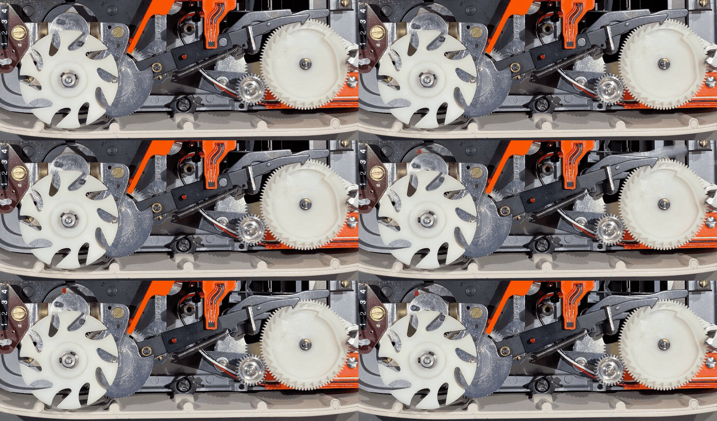
Similarly, for the new day mark, it was tracked the movement of the lever responsible for the increments of the days by one. This lever was used on the Dator series (the full date version); in the Cifra 5, this lever has no use. To simply test if the minute pulse has triggered a new day, you just have to compare the previous read of the sensor and a new read after the pulse; if the status of the sensor has changed from On to Off, the whole display will show "00:00". You can see in the picture below the magnet holder on the lever and the hall sensor hall on the bottom sensing the lever movement.
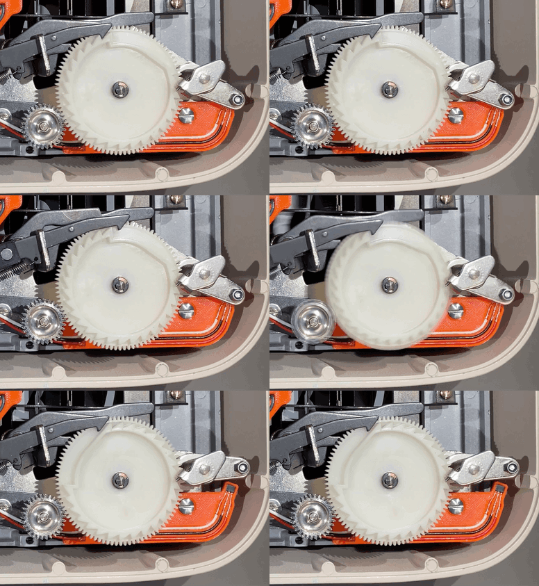
With an STM Nucleo board, I started to implement the algorithm to adjust the time; immediately, I realized it was impractical to use only the minute pulse since there was a time limitation on how fast it would be processed reliably by the clock.
In the worst-case scenario (the clock has an initial time of "00:01" and you need to set it at "23:59"), you can end up sending roughly 48 x 60 pulses for a whopping total of 2,880 pulses, which would take about 10 minutes! A different approach was necessary to speed up the entire process: I needed to install a mechanism to advance the hours faster. As usual, no drilling or modification of the original part was allowed.
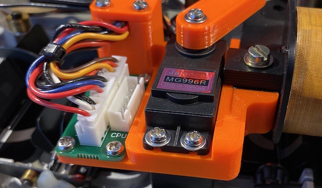
When the minute's digit shows "00", I could increment the hours by moving the same lever used to generate the hour mark signal; the lever had a 6 mm tall pin marked in red. Initially, I tried to move the lever with different solenoids, but they weren't strong enough. A better solution was to use a high torque servo, and I found the MG996R was the perfect one; it had just enough force to move the lever. There was enough space to accommodate it in an empty area inside the clock. The servo was powerful, and I took some precautions to avoid any damage: I used a PETG 3D printed lever instead of the usual aluminum one, so in case of a misalignment of the servo, the lever would eventually bend, but it will be unable to damage the clock components.
The firmware, once it had set minutes to "00", will position the lever close to the red pin to allow a quick movement to increment the hours; it will keep increment the hours till they reach the desired value, then it will move the lever l back in the parking position.
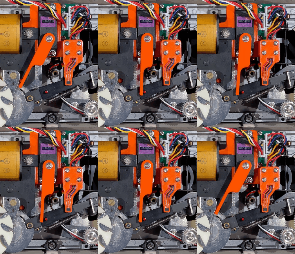
Without the original mechanical drawing, a Ziplock bag full of scrap parts is testimony of how difficult it has been to design the exact plastic part to adapt to the clock's mechanism. I created every piece with direct measurements using my caliper. A lot of trial and error was necessary to find the perfect fit with adequate tolerances. I printed all the parts with Prusament PETG using a precision of 0.10 mm; for the servo holder, a lower resolution of 0.20 mm is sufficient.
The control board
The coil is a massive inductor working at 24V; it draws 13 mA to flip the palette. I start to play with the coil feeding the control voltage, alternating the terminal, and observing the advancement of the numbers. Soon I got an unpleasant reminder: all inductors have back emf; this, in particular, can reach hundreds of volts!
I opted for a small motor IC driver with an integrated H bridge, complete with all the logic drivers and current limiting; I needed to add a few additional components to make it work. You have to feed the IC with two inverting logical signals, and the clock will be back to life. The IC is the DRV8871 from Texas Instruments; I also included a TVS diode to protect the internal bridge from undesired overvoltage, even if the IC performs a perfect coil commutation with no spikes.
I initially thought to use a dedicated 24V power supply and an LDO to power the MCU and display. Still, after careful consideration, I decided to use a simple USB power supply and a boost converter to generate the 24V necessary to the coil; 13 mA were in perfect reach of a simple boost IC. For the job, I chose the TPS61041, a fully integrated DC-DC boost converter; Two 4.7 uF on the input were adequate to supply the current needed for the boost. Since the load was highly inductive, there wasn't any inrush current that could overload the converter and lower the 24V rail. The prototype showed a very smooth behavior like the coil was powered directly from a bench power supply. To further stabilize the 24V supply, I installed close the IC solenoid driver an electrolytic capacitor of 22uF.
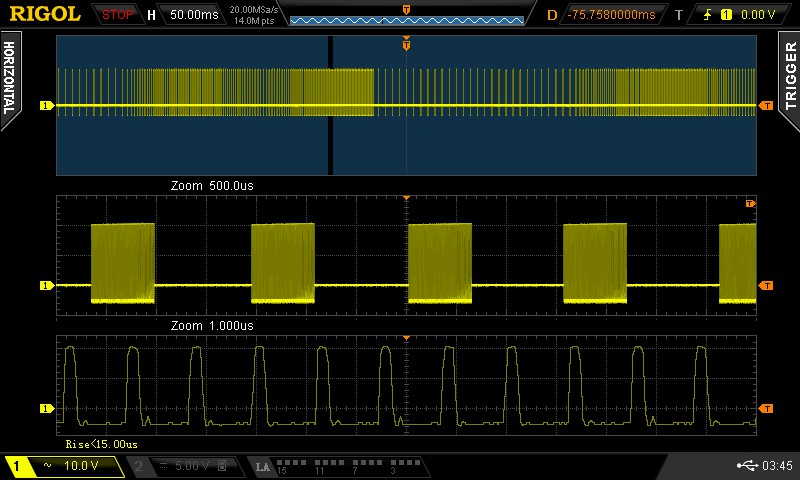
The servo requires just 5V to work; the current consumption goes up to 1.1 Amp to move the lever. I've installed a 470 uF close the servo terminals to smooth its current inrush.
The movement control is the standard one used in all servos, where the duration of a pulse every 20 ms determines the position of the actuator. Below are some typical examples of how to move the actuator.
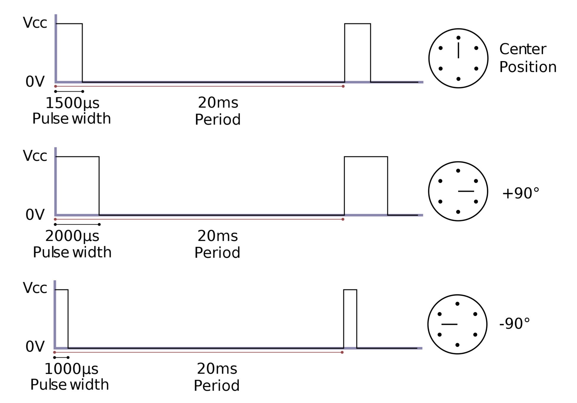
I used a logic MOSFET BSS138K with integrated ESD protection to interface the pulse input of the servo from the microcontroller, even if the total capacity of the gate is relatively small (100 pF), I usually insert a small resistor to limit the slew rate from the MCU I/O pins and to help limit the current through the ESD protection.
The Hall sensors are the usual A1344 which you can find by the bucket on Amazon. To interface the signal with the MCU, I used the same logic MOSFET BSS138K.
The MCU is an STM32 M0+ family is a pretty recent processor; this model has a Nucleo 32 dev board I used to test all the interfaces before commencing the PCB design.
Unfortunately, the 32 pin version is without the Vbat pin, so I added additional components to manage the standby state: I used a CR2032 lithium battery to power the entire processor, and a generic input pin to monitor the main 3.3V rail every 10 ms. As soon as the power was down, a particular routine put the processor into a deep sleep. An MCP100 will send a wake-up pulse once the power is restored and stable for 350 ms. It sounds a little complicated, but this solution allowed me to play with different sleep modes and measure the relative absorption. The MCU implementation is completed with a fault pin and a four-pin header to connect the programmer.
An LDO takes care to generate the 3.3V required to the MCU and the display. The regulator as an embedded soft start avoids inrush current for the capacitors.
I used three buttons (Set, Up, and Down) and a two-color 0.96" I2C OLED display module for the human interface.
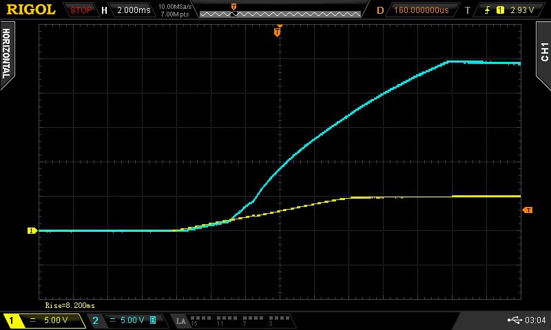
Since the 5V rail has a 470 uF connected (more than the 10uF allowed by USB specs), I used an adjustable current-limited power switch to limit the inrush current of the USB power supply. A resistor set the maximum current to 1.4 Amp; the final result was a very smooth initial powerup of the device, including the boost converter.
A portion of the main PCB was pre-cut to have a mini PCB to accommodate all the connectors from the servo and HALL sensors; these signals were grouped in one harness to simplify the wire management inside the clock. Connecting all the female pins to the wires was quite tedious; still, the final result was worthy of the effort. The cable management inside the watch was very tidy and professional!
Firmware Overview
The firmware runs on FreeRTOS with three cooperative tasks communicating exclusively
via xTaskNotify — no queues, no mutexes, keeping the footprint minimal on
the Cortex-M0+. This implementation uses the native FreeRTOS API directly, not the CMSIS-RTOS
wrapper provided by STM32CubeIDE — I found the direct API clearer after studying the
FreeRTOS manual. The code is organised into focused modules:
rtos_initdisplay_taskbutton_taskclock_taskrtc_helpersssd1306
Mode of Operation
On first boot (or after a dead coin cell), the firmware detects that backup registers are empty and launches a setup wizard that chains three screens: silent hours (HH-HH), RTC smooth calibration (±NNN), and time setting (HH:MM). Each screen uses digit-by-digit editing with the three tactile buttons: SET advances to the next digit, INC/DEC modify the current digit with validation and clamping.
Once the time is set, clockTask takes over and enters the synchronization phase. It first checks if a previous mechanical position was stored in backup registers — if so, it performs a fast re-sync by advancing the mechanism from the known position. If no position is stored (true first boot), it performs a sensor-based zero search: pulsing the coil repeatedly while reading the two Hall effect sensors to find the minute zero position. Once minutes are synchronized, the servo engages the hour lever to set the correct hour. The OLED displays progress messages throughout this process.
After synchronization, the clock enters normal mode. Every minute, at the RTC second rollover, clockTask sends an alternating-polarity pulse to the coil to flip the next minute palette. The mechanical position is tracked in backup registers (DR0 for hours, DR1 for minutes) and compared against the RTC to detect drift. At the top of each hour (:00), the servo briefly engages the hour-increment lever to advance the hour display.
Silent Period
The silent period (default 22:00–09:00, configurable) suppresses the mechanism during nighttime hours. The clock is allowed to tick to :00 before going silent, then stops all coil and servo activity. When the silent period ends, the mechanism catches up to the current RTC time — advancing minutes rapidly and setting the correct hour — so the display is always correct when the period is over.
Settings and Persistence
Silent hours and RTC calibration are stored in RTC backup registers, which survive power cycles as long as the coin cell is alive. They are additionally persisted to Flash page 31, so even a completely dead battery won't lose your settings — on the next boot, the firmware restores them from Flash.
The RTC smooth calibration allows compensating for crystal drift by adding or removing up to 511 pulses per 32-second window, directly using the STM32's built-in calibration hardware.
Display and User Interface
displayTask owns the SSD1306 OLED and implements a 6-state UI machine: idle clock (HH:MM), time setting, silent hours editing, RTC calibration, synchronization progress, and error display. The display auto-powers off after a timeout to save power; any button press wakes it without forwarding the event to the UI, preventing accidental sub-menu entry. From the idle clock screen, three long-press actions are available:
- Long SET — enter time setting (blocked during silent period)
- Long INC — edit silent hours (HH-HH)
- Long DEC — edit RTC calibration (±NNN)
buttonTask scans the three tactile buttons with software debounce. Short presses fire on release, long presses fire after holding for one second. After sending a notification, the button task suspends itself and waits to be resumed by displayTask — a simple flow-control mechanism that guarantees events are processed one at a time.
The display driver is a buffer-less SSD1306 driver evolved from Stefan Wagner's original, with scalable font rendering (4 sizes from 5x8 to 20x32) and no RAM framebuffer — essential for the tight memory budget of the STM32G031K8.
Conclusions
I love my clock, and I enjoy the flipping sound of the palette; it's a good reminder of the passing time…