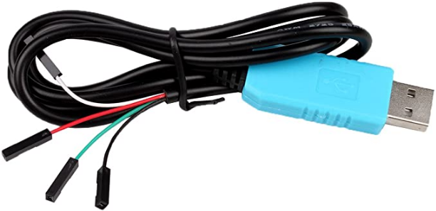
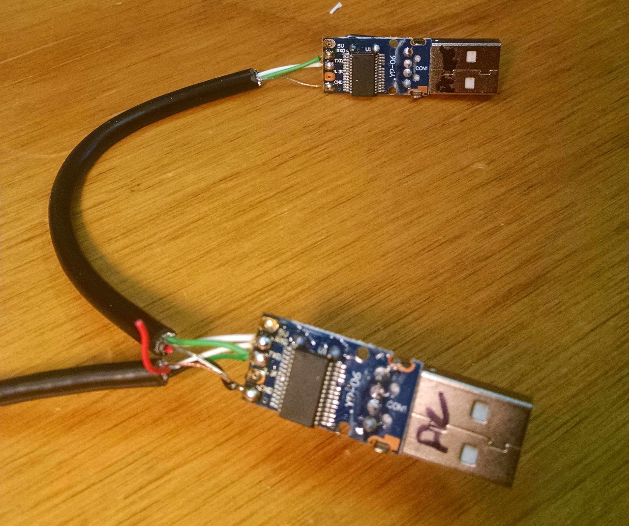
I had a couple of USB serial TTL adapters with cables that had dupont connectors on the ends. These were great for using with microcontrollers or hacking around with embedded devices. They had a +5v (or +3.3v if you cracked them open and warmed up the soldering iron), which I didn't need for this, but they were what was on hand.
 A spudger to split the halves of the case open, and a little work with the soldering iron and I had the old cables removed and set aside for the next project. They weren't quite long enough for my setup, and I really wanted something shielded.
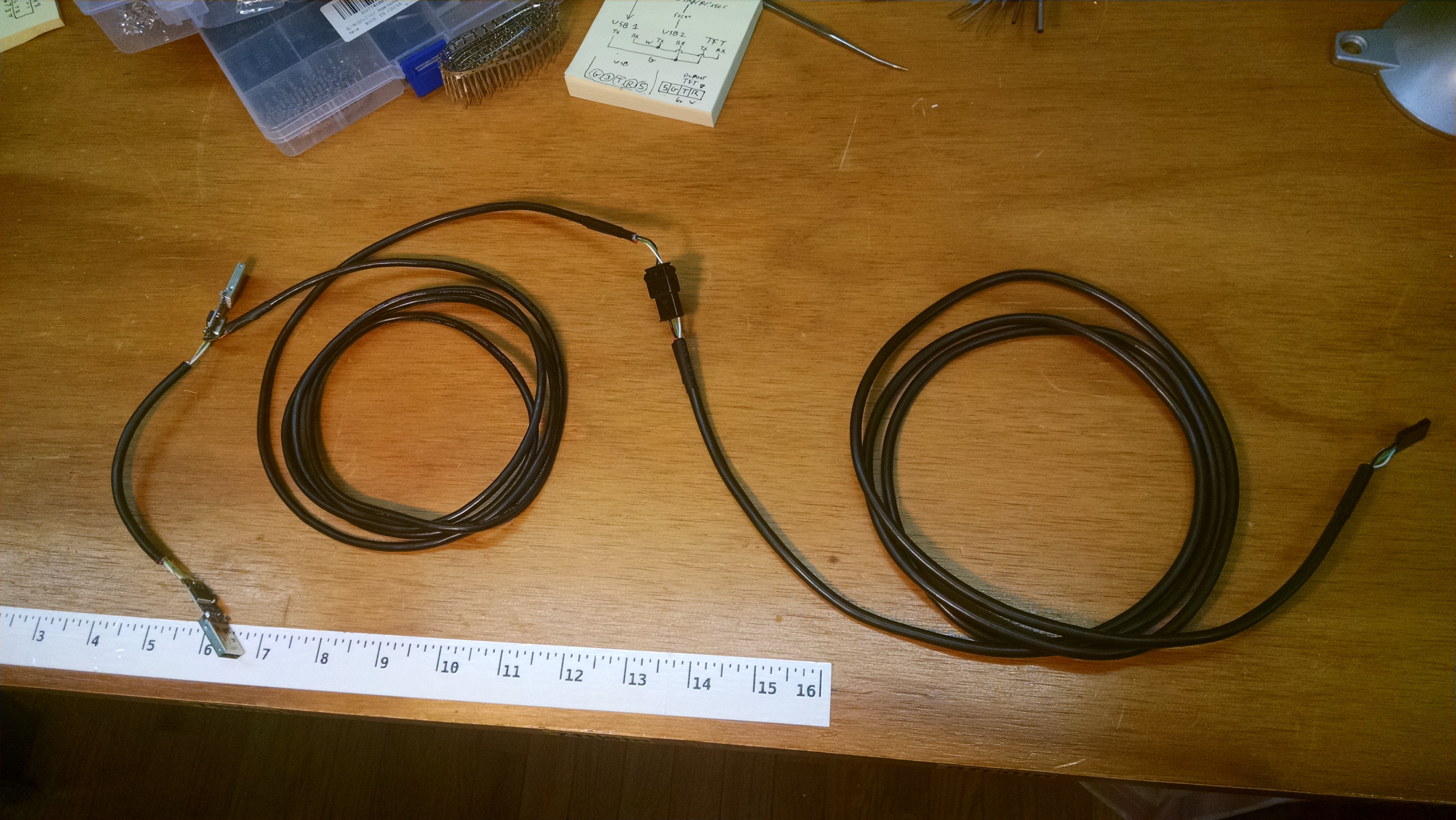
I found a few old USB cables in the parts bin that were missing some ends that were just about perfect. The length wasn't quite right, but two of them end to end looked good, and having a connector near the back of the printer would make installation and future maintenance easier. A bit of soldering and crimping later, and this emerged:


Everything is wired as per the diagram in the previous log. The far end has a dupont connector with the pins arranged to match the pinout of the TFT28. My best reference for that was the manual for the GEN_L, with the pinout for the AUX connector, so there's a slight chance it's mirrored, but once I get the printer open I can verify the pin markings on the actual TFT28. Thankfully they are printed right on the PCB. The connector in the middle of the cable is a JST-SM. I chose it both because I find them slightly easier to crimp than dupont, and because they lock together. The short jumper between the two USB serial-TTL adapters is just soldered.
On the short jumper I connected the shield of the cable on both ends to GND. On the long cable from the serial-TTL adapter, the shield is connected to GND. In the middle of the two long cables the shield is not connected, as I had already cut it off. Oops. To make up for this, the dupont end of the other long cable has the shield also connected to GND. I intentionally did not want the shield connecting both GNDs together, as I had some vague memory of ground loops or something.
The next step will be to install it, both on the RasPi and the printer, and then sort out the software side of the things.
 SetecAstronomy
Discussions
Become a Hackaday.io Member
Create an account to leave a comment. Already have an account? Log In.