First prototype had a few main issues that blocked the project for some time:
- Problematic LED placement on the side - they didn't fit due to the plating thickness.
- A lot of sidelights that light up the next element in a stack.
- Bad design of castellated holes.
- Absence of the mounting features for acrylic parts.
- Acrylic parts by themselves.
Before going too much into details and design decisions, I want to say an enormous "Thank You" to PCBWay for sponsoring the new PCB design and helping me with my design questions.
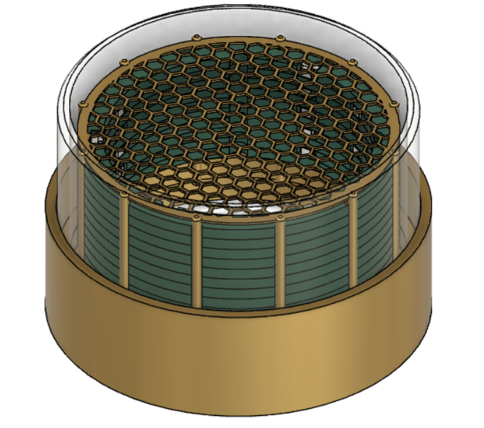
From a previous iteration, I learned one super important lesson which is "Don't start without a proper plan". So I designed the end device in Fusion360 to have a visual representation of the whole assembly, and it helped me a lot during the design process!
Let's go through all of the issues that were described above one by one.
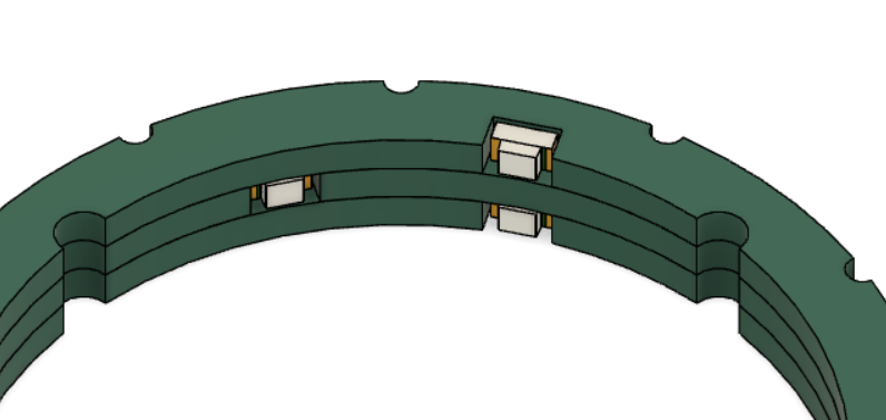
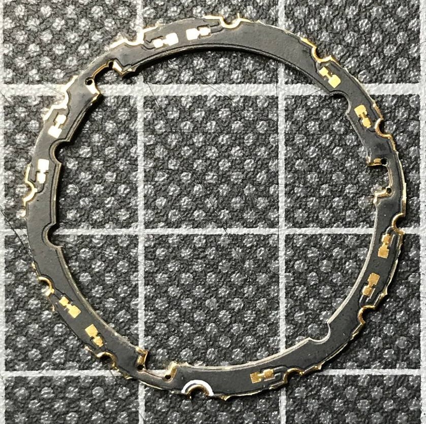
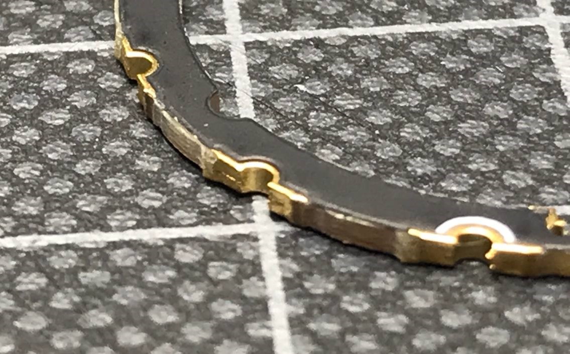
- The problem with LED placement was easy to fix. I changed the footprint for the LED to compensate for gold plating, put the LED deeper, and added the vias in corners to compensate for the radius of a cutting tool.
- There was also an easy fix for an incorrect design of the edge plating and castellated holes - I just followed these two guidelines from PCBWay webpage for castellated holes and edge plating.
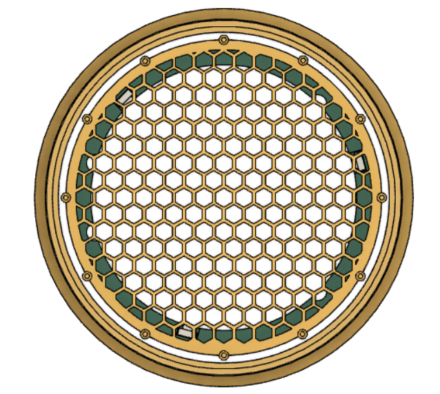
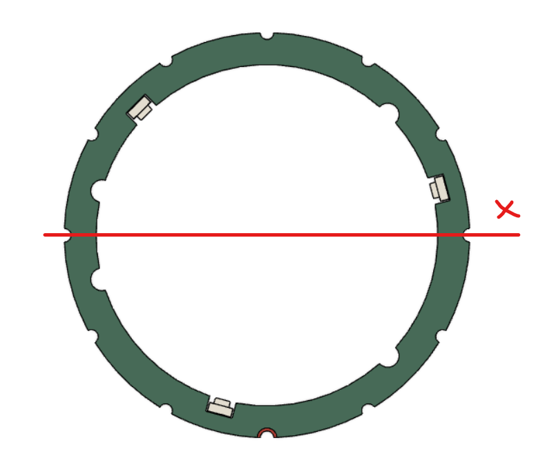
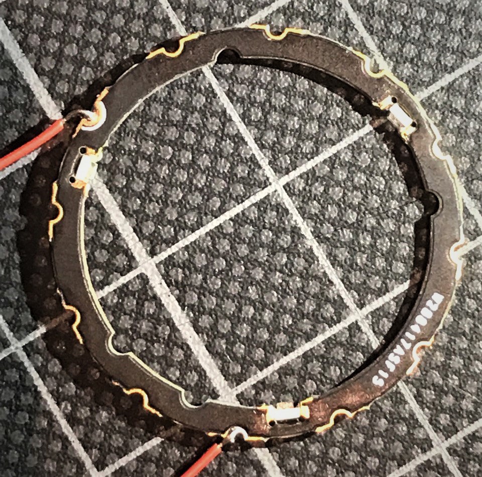
- Sidelight emission and the absence of mounting features for acrylic parts were fixed with what I call a "flippable" PCB. The new PCB is designed in a symmetric way, which means that I can flip the PCB around the x-axis and have the mounting half-holes in the same position.
This approach gave me the possibility to use the same PCB to prevent sidelight from a previous segment and reduced the cost of the design as a whole (gold-plated edges are expensive!). Now I can use one PCB instead of two, as it was in the initial idea.
After fixing all these issues and designing the whole assembly in CAD, making a new PCB was super easy - simply exporting DXF, placing holes and LEDs on already predefined spots.
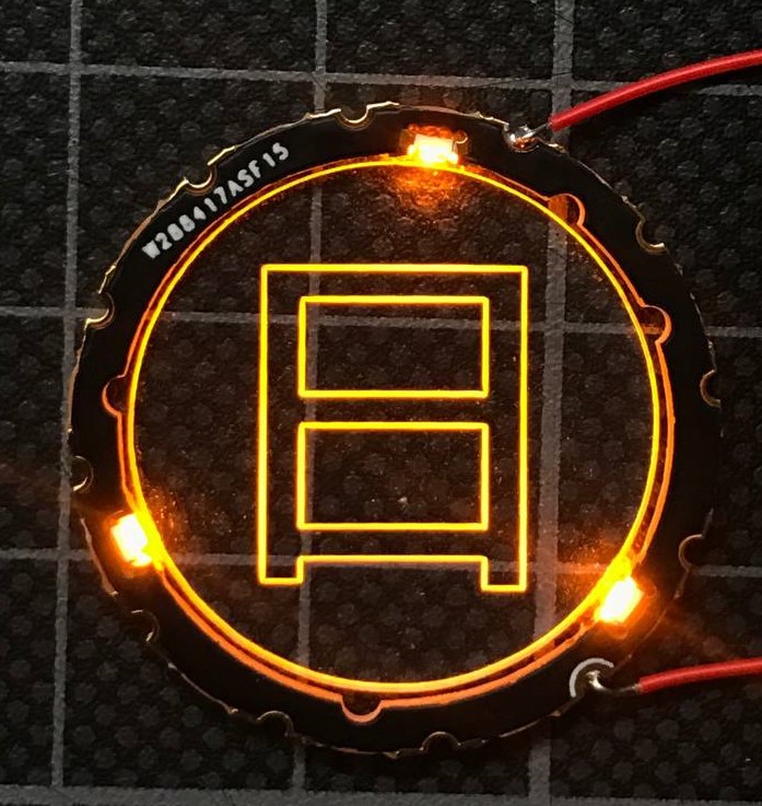
Two weeks after that I received my PCBs from PCBWay! As expected, boards look nice and all previous issues are gone.
LEDs are fitting perfectly this time:
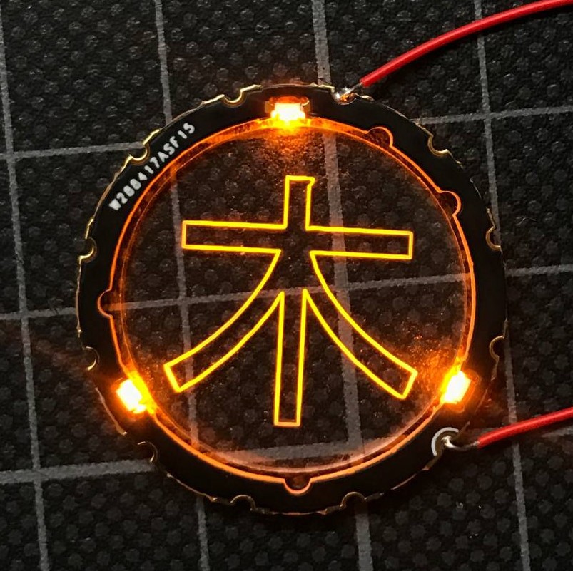
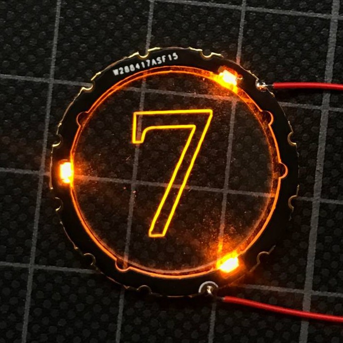
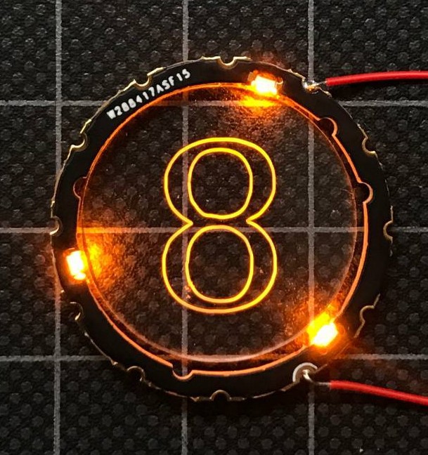
And the last problem in the design was the acrylic parts. I ordered some samples some time ago before redesigning the PCB. They are smaller than the new ring and don't have mounting features but they are still a good visual representation of the final result.
The next steps will be ordering proper acrylic parts and making the first full assembly. I hope that these small steps will not take another year))
And finally, I want to thank PCBWay once more for supporting this development. If you are looking for a PCB manufacturer for your project PCBWay would be definitely my first recommendation!
Cheers...
Discussions
Become a Hackaday.io Member
Create an account to leave a comment. Already have an account? Log In.