 ByteTech
It has taken a while to get here. This is my first project since my accident and I can't move too much right now and have many other issues to work through so can only do an hour or so on this every now and then, but it's a fun and frustrating project so far.
I've managed to get to the point that with an X5s and a single TB50 plugged in, I can boot it up, both the X5s and FPV gimbles calibrate, and the controller connects and shows a live feed of both cameras. So far so good!
The next stage, and this is really what will make the difference between this being interesting, and this being actually useful is getting it to record.
So here's my current issues:
- The app on the monitor forces me to be in photo mode. Each time I switch to video mode it goes into a "loading" screen saying "Switching SD mode" and after around 15 seconds switches back to image mode again.
- The SSD doesn't always show up and when it does, it never completes a format
Now, it may be argued that this is a software issue, but I think it must be to do with one or more components rather than software. The controller, gimbal, card, battery, and monitor (which is running the app), when plugged into a fully working Inspire 2 works absolutely fine. This means that it's nothing to do with the app, just the telemetry it's receiving. My guess is, I've either not got something plugged in correctly, or a component is broken and as a result the app is receiving incorrect information.
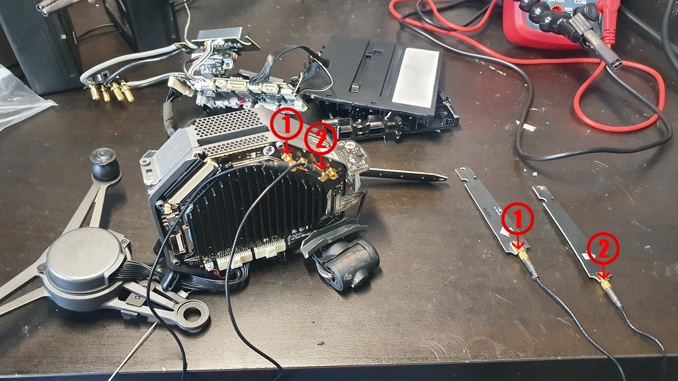
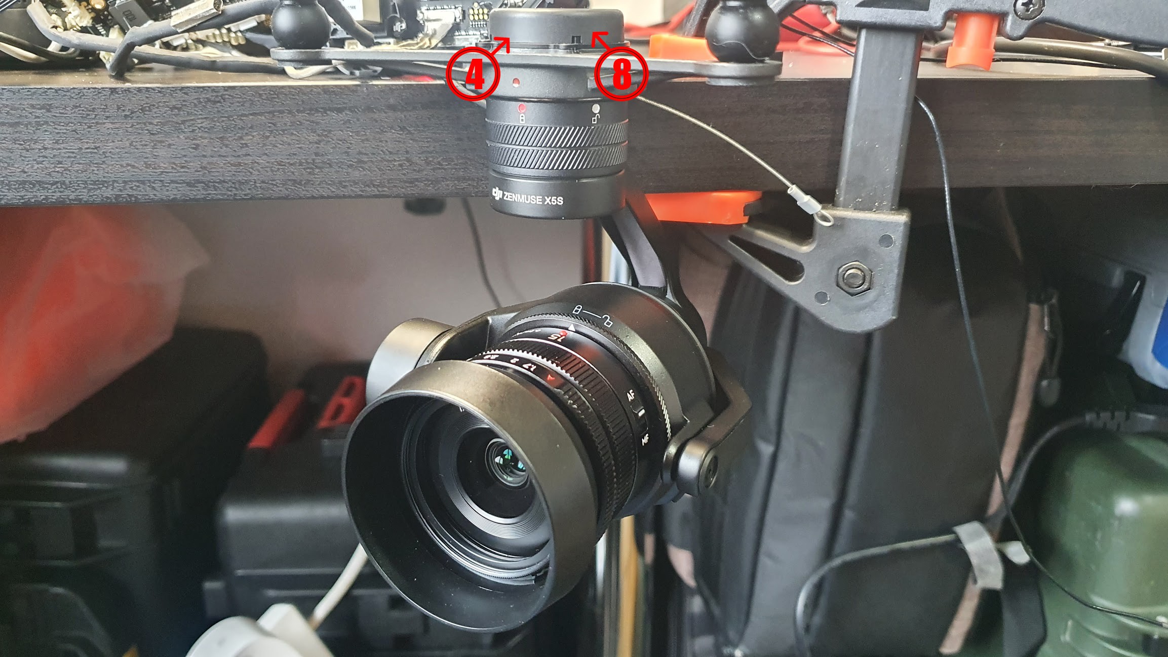
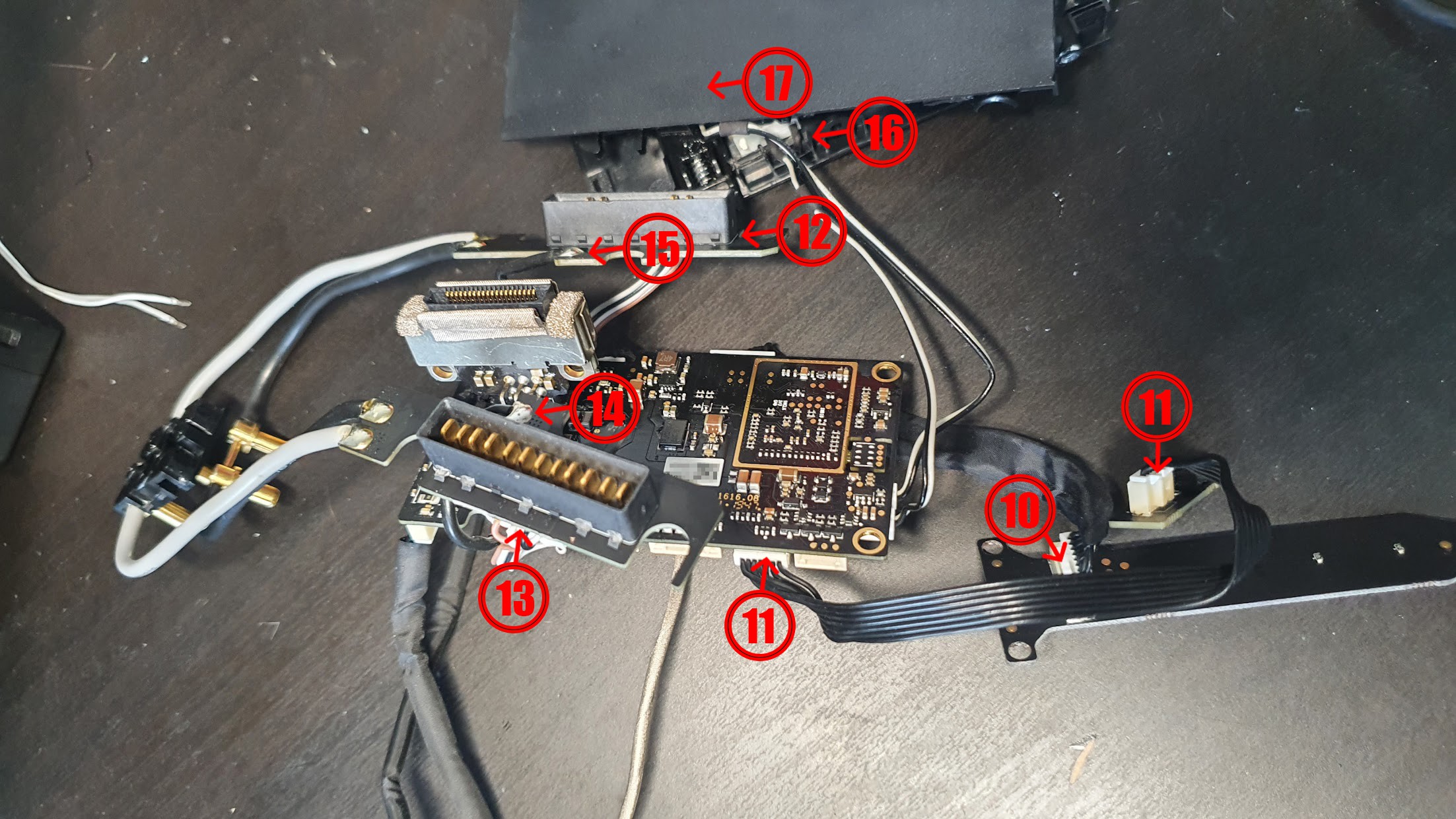
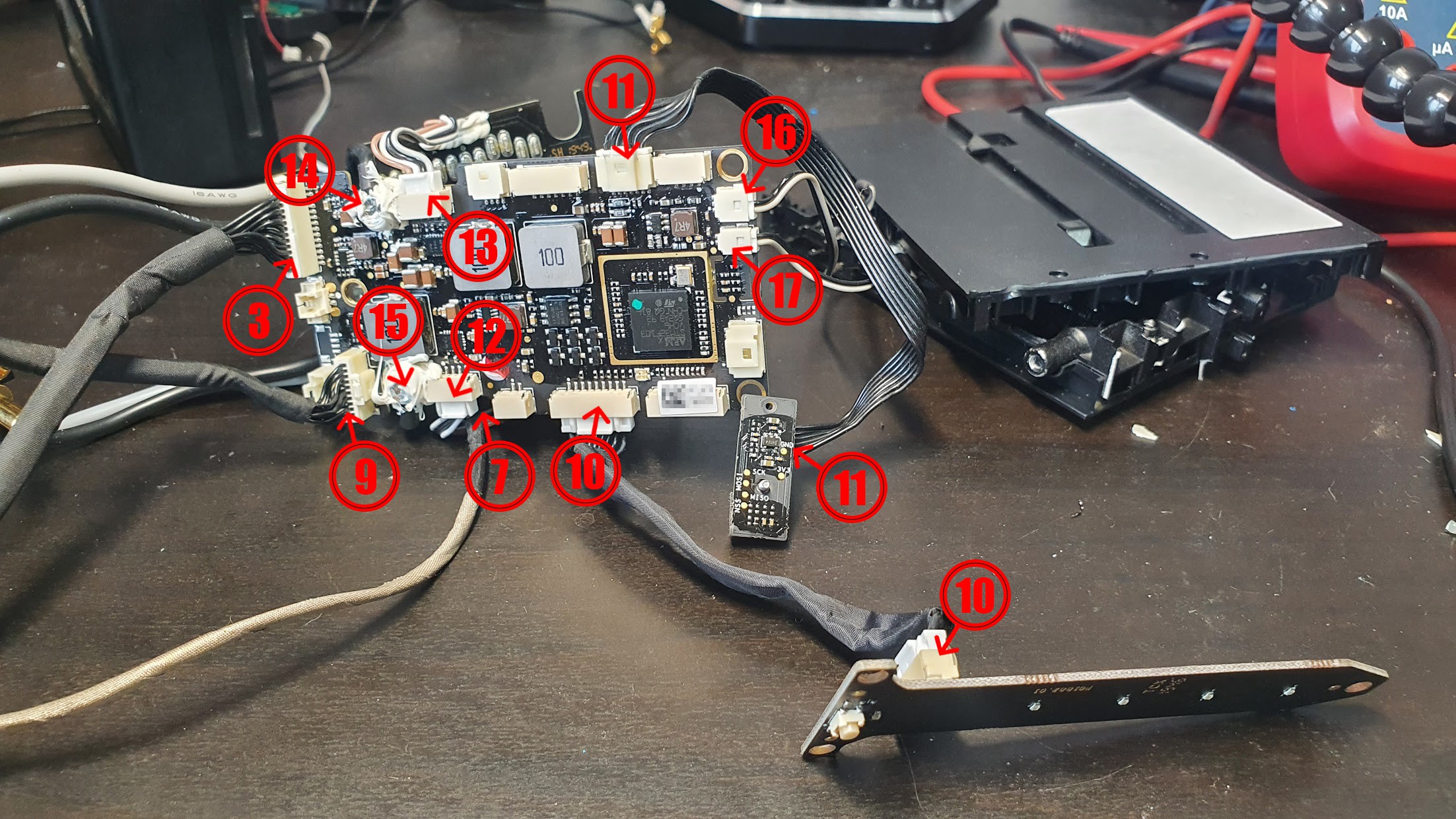
I have no idea where to go from here so to help here, I've taken photos of all the components I have in use, with each used port/cable labelled at each end, to show what is plugged in where. For example "1" shows where a specific cable is plugged in at each end (one end may be in a different photo to the other but each number only represents one cable/wire).
Here are the photos:
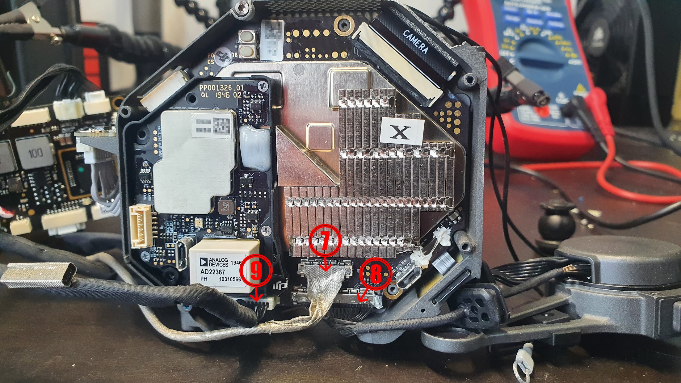
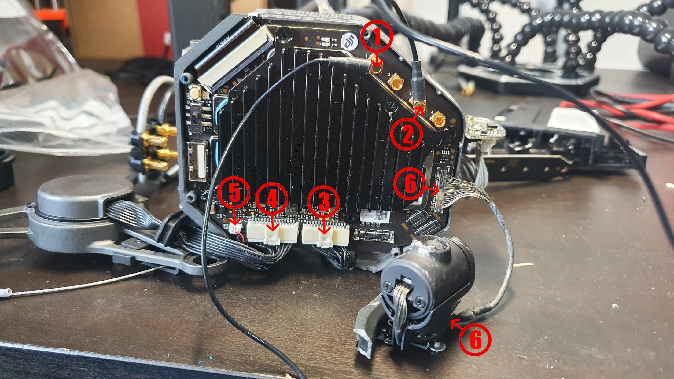
Just through working on it so far, and not from anything I can find online, my understanding (based on guesswork) of the purpose of each of these is:
- Antenna
- Antenna (there are two more antenna ports but unfortunately the cables and antennas were too damaged for me to use, 2 should suffice though
- Unknown
- Gimble control
- Unknown
- FPV camera feed and gimble control
- Data feed from flight controller body to the SSD port (presumably the video feed is sent down this cable to be saved to the SSD card)
- Video feed for main gimble
- Unknown
- Power button
- Unknown (This was a sensor which was fitted in the middle of the block that the batteries used to slot onto but not sure what it actually is
- Battery 1 power supply
- Battery 2 power supply
- Unknown (Presumably Battery 2 ground or similar)
- Unknown (Presumably Battery 1 ground or similar)
- Switch checking if Battery 1 is locked in place
- Switch checking if Battery 2 is locked in place
The only components which have been removed that I'm aware of seem to be:
- Motors
- ESC's for motors
- GPS module (undamaged and have cable, I've just not plugged it in as not needed)
- Downward facing distance sensors and landing cameras
- Upwards facing distance sensors
- Forward facing distance sensors
- Landing gear motor
So, that's the project as it stands, any help from this point would be really appreciated. Thanks all!
Discussions
Become a Hackaday.io Member
Create an account to leave a comment. Already have an account? Log In.