A Better Backplane
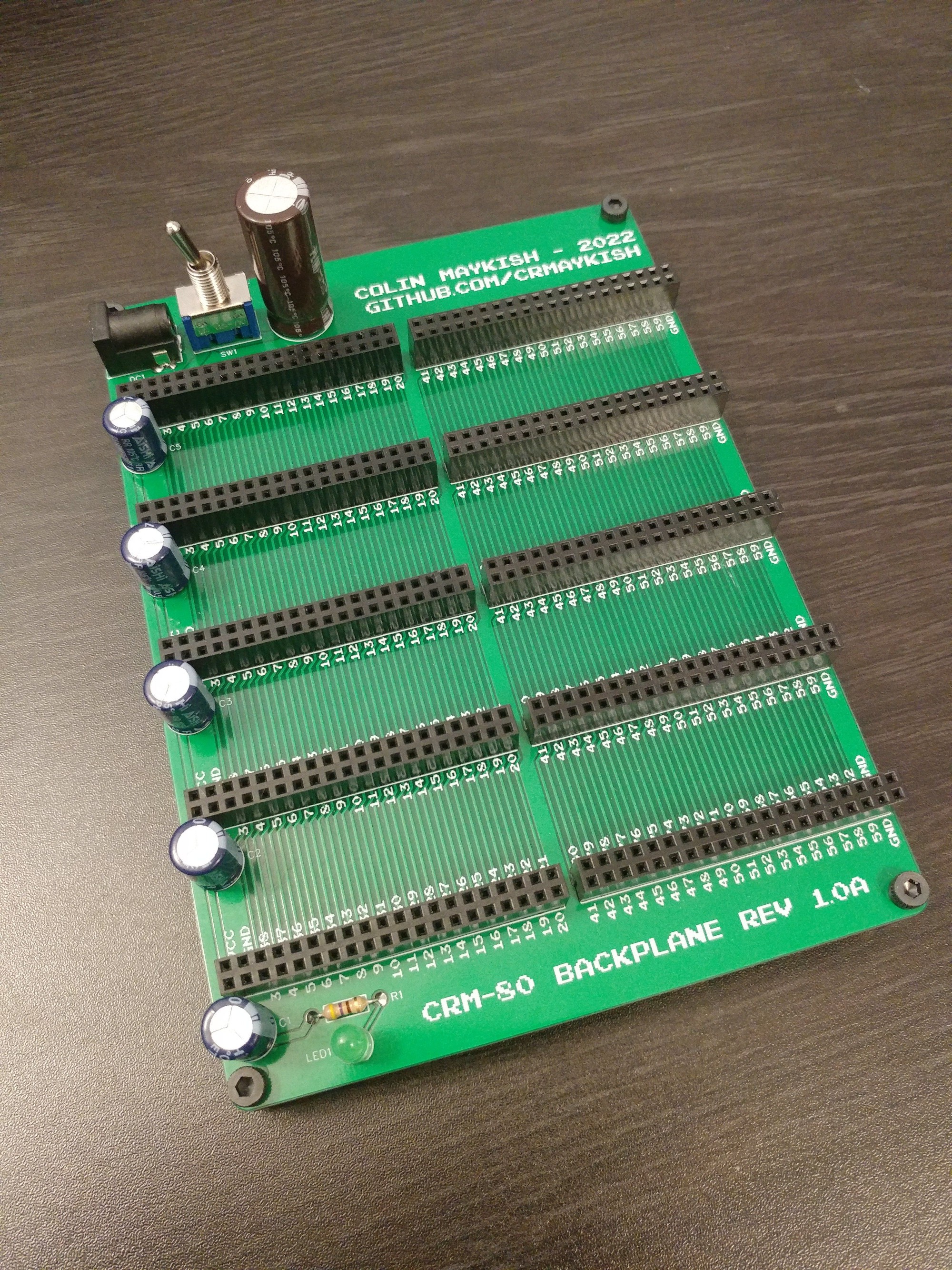
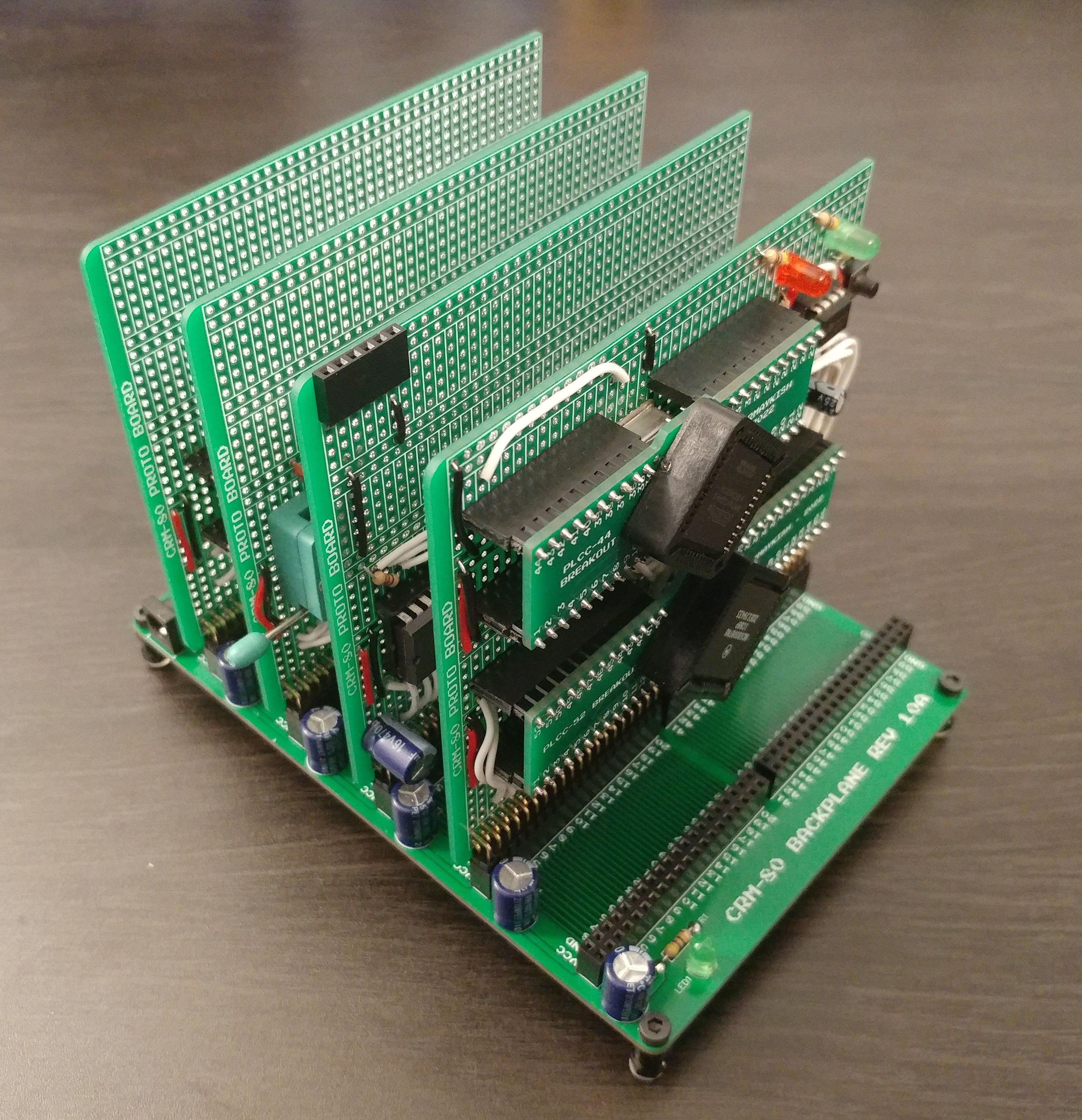
In the long run, I don't know if Mackerel will be a backplane system or a single-board computer, but while the project is still in the prototyping phase, having interchangeable component cards on a backplane does make development easier. The first build (shown in the previous log) repurposed a 40 pin backplane from an earlier project of mine, but I quickly ran out of pins and space on the PCBs for all of the ICs and interconnects I need. To give Mackerel some more room to grow, I designed a really simple 80-pin backplane and matching prototype PCBs.
PLCC Breakout Boards
Another bottleneck in the previous build was using the DIP-48 version of the 68008 CPU. Using the PLCC package gets you two more address pins, an upgrade from 1MB to 4MB of address space. I'm not sure of the minimum RAM requirements to run something like uCLinux, I'm sure it depends on the version and features. I've seen projects boot ancient versions of Linux with as little as 512KB, but I'd prefer to target something more recent. Linux has not gotten any smaller...
Anyway, PLCC packages are not the hardest surface mount chips to work with, but they are more difficult to use in prototypes, so I designed some PLCC-to-DIP adapters for the various sizes.
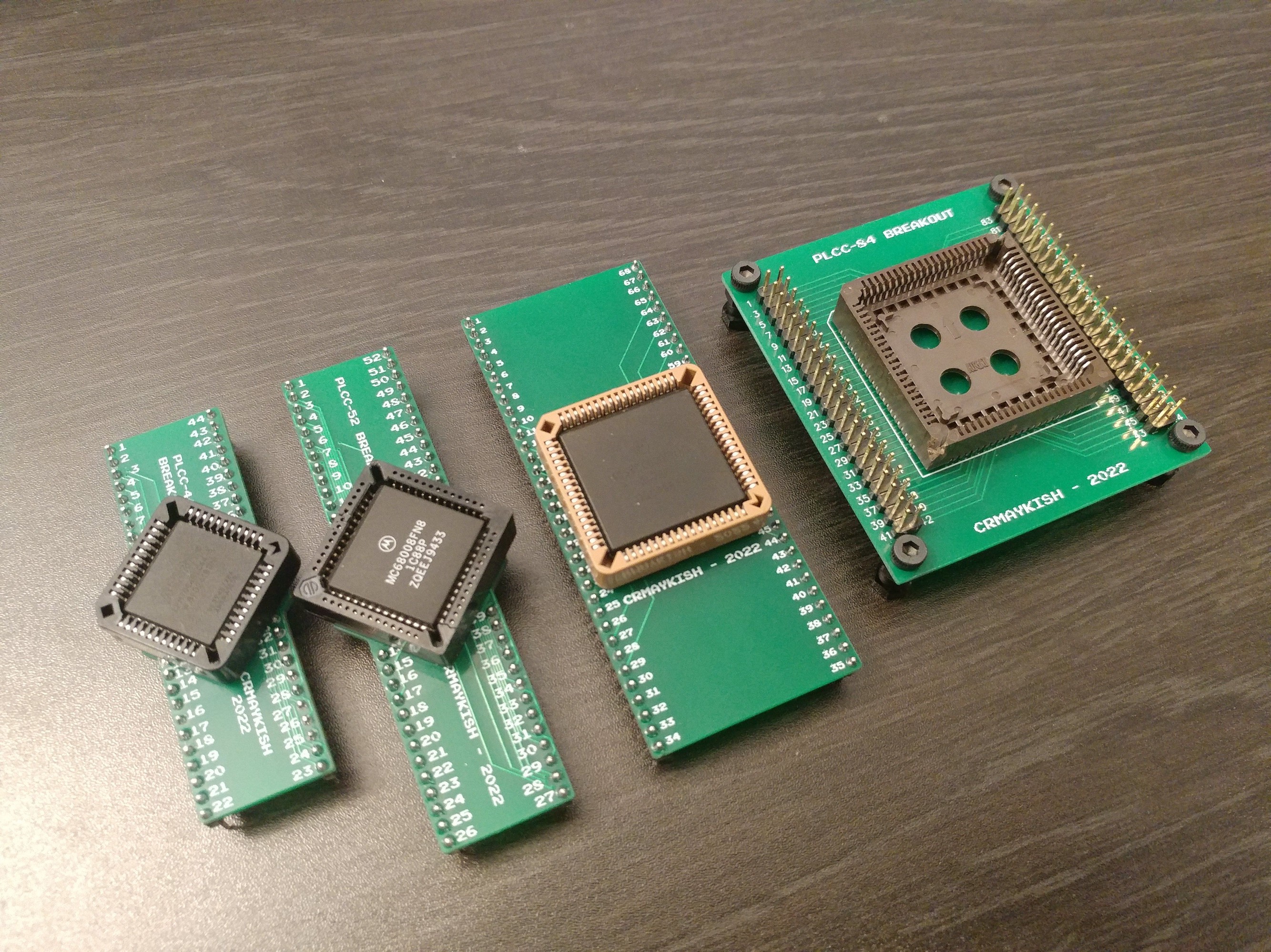
The first two (PLCC-44 an PLCC-52) fit nicely into a normal breadboard or perfboard. Technically so does the PLCC-68 version, but it takes up two lanes on a breadboard which makes it a little space inefficient. The MC68EC000 uses this package. That CPU has the option for an 8-bit bus and supports higher clock speeds and more address space. It might be a nice upgrade to the 68008 at some point.
I also ordered a PLCC-84 breakout, but this is proving to be less useful. The only ICs I currently have in that package are some non-functional EPM7128 CPLDs.
CPLD Development
Speaking of CPLDs, I've swapped out the multiple GALs for a single EPM7064SLC44 CPLD. These run at 5V and can be programmed using Quartus 13.1 and a cheap USB blaster. This version of Quartus is still available for download on the Intel website and runs just fine on Windows 10. The USB blaster is a $5 clone from eBay. It also works fine.
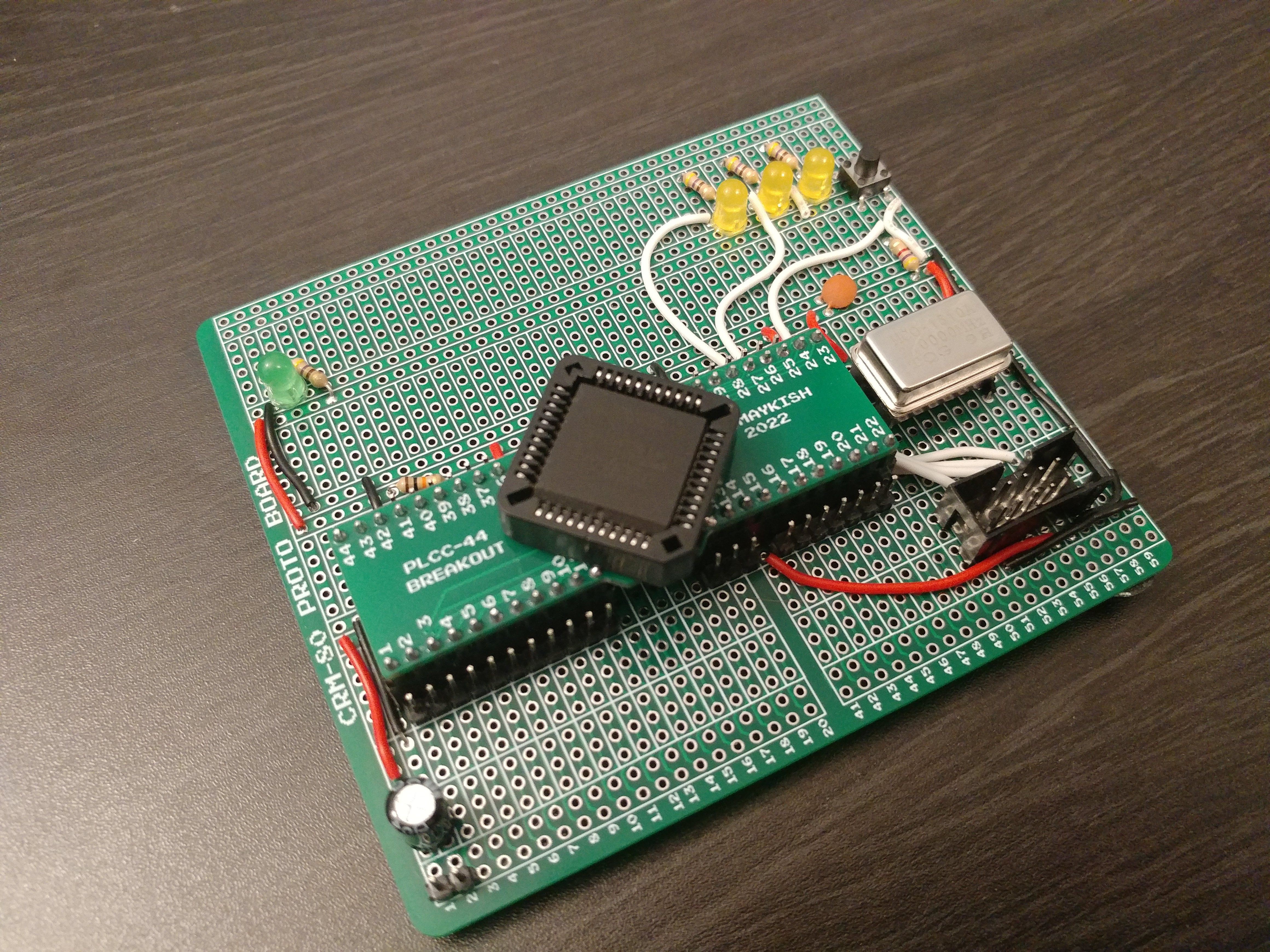
I put together a breakout board for the JTAG header, a clock, and some I/O to make chip testing and programming faster. The PLCC sockets seem pretty fragile and they're expensive enough that I don't want to squander them, so moving around the whole DIP adapter seemed like an acceptable compromise.
As far as the actual programmable logic, I've used this CPLD to implement:
- Two clocks from the 50 MHz oscillator
- one for the CPU (5 MHz)
- one for the MFP (1.25 MHz)
- Address decoding for memory and MFP peripheral
- /BOOT signal to map ROM to 0x0000 at reset
- DTACK generation - no wait states for ROM or RAM, MFP DTACK when MFP is selected
State of the Hardware
Basically, I've rebuilt the first prototype of Mackerel on the new 80-pin backplane and moved all the control logic onto the CPLD.
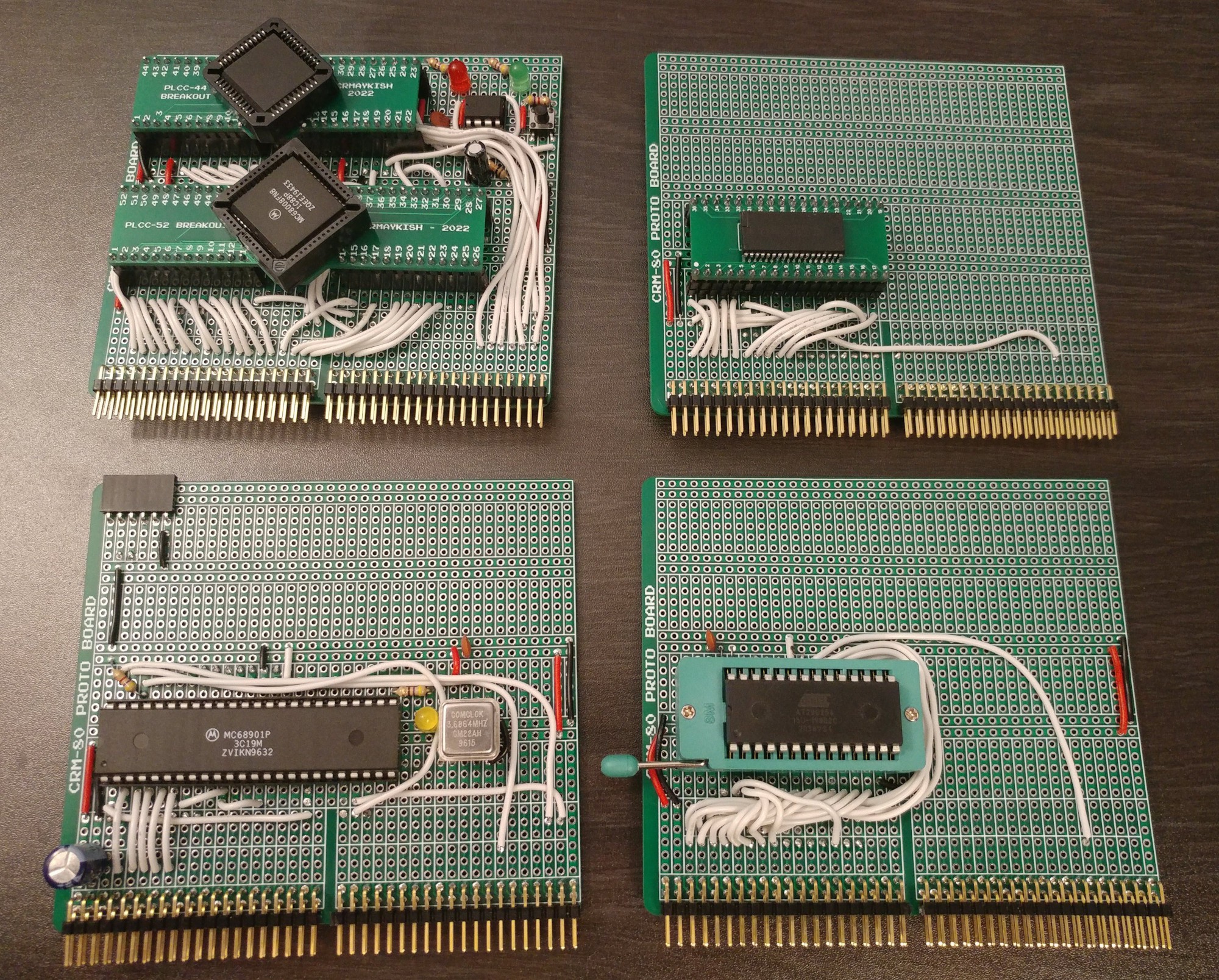
Here it is assembled on the backplane.
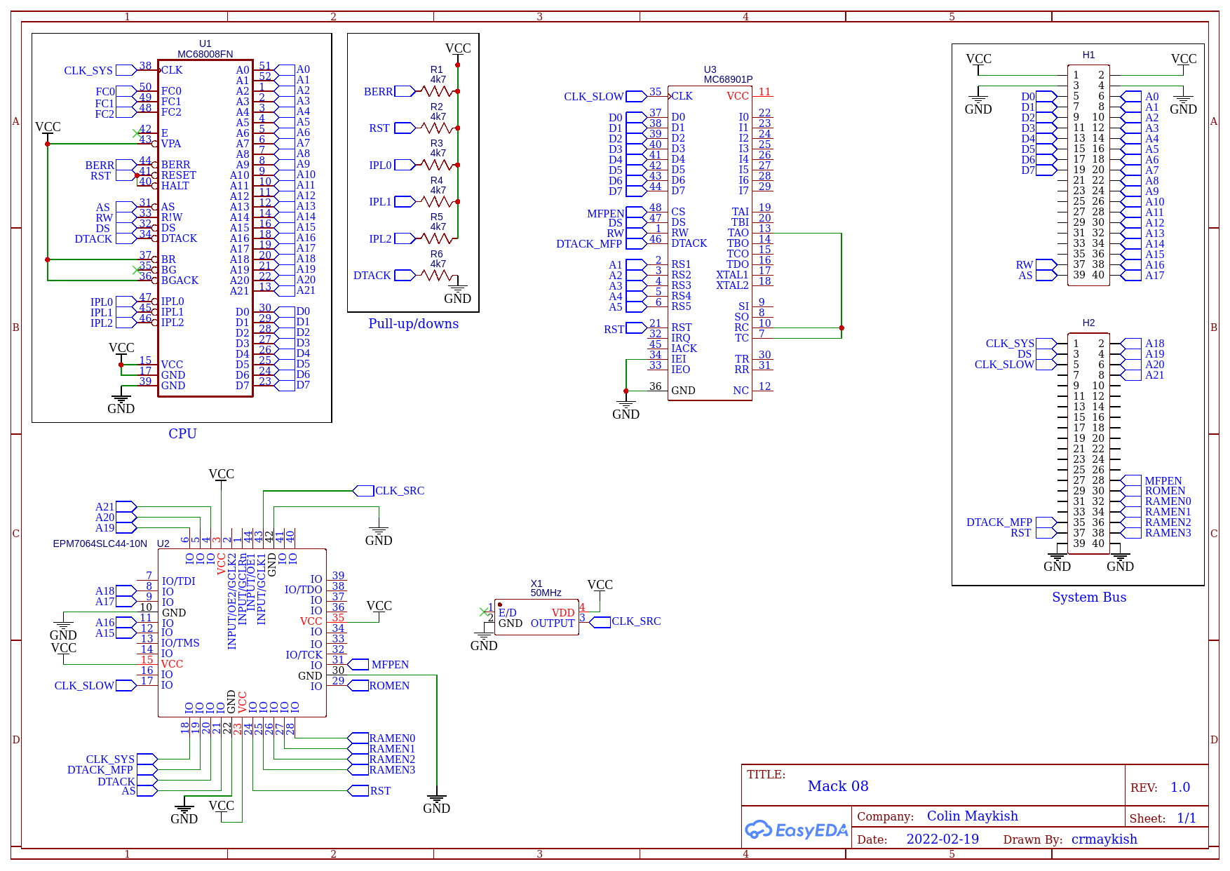
Here's a mostly accurate schematic of the current system. This ignores the ROM and RAM, but those are mapped as expected, address and data bus to the CPU with chip-select signals coming from the CPLD. Nothing about this design is finalized. A lot of the routing is just there for convenience. The system bus on the backplane headers is not well thought out yet. I'm still just adding signals as needed to get them connected between the component boards. There is plenty of room for consolidation once I've proven out the design.
Problems with the MFP UART
The only I/O in the system is the MC68901 MFP board. In theory, the MFP provides a little bit of everything you'd need in a barebones computer system: timers, GPIO, and a serial port. The first two work pretty much as expected. I can blink LEDs with the GPIO and generate clocks and delays with the timers. The serial port, on the other hand, has proved more difficult to use. I've spent many hours trying different combinations of clock speeds, chip-select and DTACK logic, and baudrates trying to get this serial port to run reliably.
It "worked" pretty much immediately upon hooking it up and it continues to work as expected for low speed communications like the serial monitor program. For some reason I have not yet discovered, the UART is unreliable for prolonged periods of time or when transferring large amounts of binary data. It works about 80% of the time, but occasionally the whole system will stop responding.
I'm finally settled on using a 5 MHz CPU clock, with a 1.25 MHz clock driving the MFP and running at 9600 baud with a clock generated from one of the timers on board. I can load and run programs over the serial port with about 95% success, but long running applications still sometimes crash unexpectedly.
The bootloader allows for loading arbitrary files into RAM from the host PC. If the files are text, they can be printed. If they're programs, they can be executed.
### Mackerel-8 Bootloader ###
> load
Loading from serial...
Done!
> print
       o                 o
                  o
         o   ______      o
           _/  (   \_
 _       _/  (       \_  O
| \_   _/  (   (    0  \
|== \_/  (   (          |
|=== _ (   (   (        |
|==_/ \_ (   (          |
|_/     \_ (   (    \__/
          \_ (      _/
            |  |___/
           /__/

> load
Loading from serial...
Done!
> run
Run loaded program
Hello from Mackerel. Here are some numbers 99 BEEF
Next Steps
I'm not satisfied with the MFP serial port. The timers and GPIO are fine, but I have recently purchased some MC68681 DUART chips. If I can get those working more reliably than the current serial port, I may scrap the MFP entirely and find another solution for the timers since the 68681 has 8 GPIO pins as well.
Once I have a reliable serial port, I'm going to design a PCB to hold a bunch more RAM. I really don't want to wire 5 or 6 more RAM chips by hand, but I think having 3.5MB of fast (10ns) SRAM and another 512KB of address space for ROM and I/O would be a great step toward booting Linux.
 Colin M
Discussions
Become a Hackaday.io Member
Create an account to leave a comment. Already have an account? Log In.
Hi, that's a great project your working on. I am also working on 68008 based computer and so far I've been using the the DIP version that also have a limitation on the interrupt levels: only 2 IPL pins instead of 3. I'd love to move to the PLCC version and I was wondering if you have shared your PLCC to DIP adapters schematics and pcb files.
Are you sure? yes | no