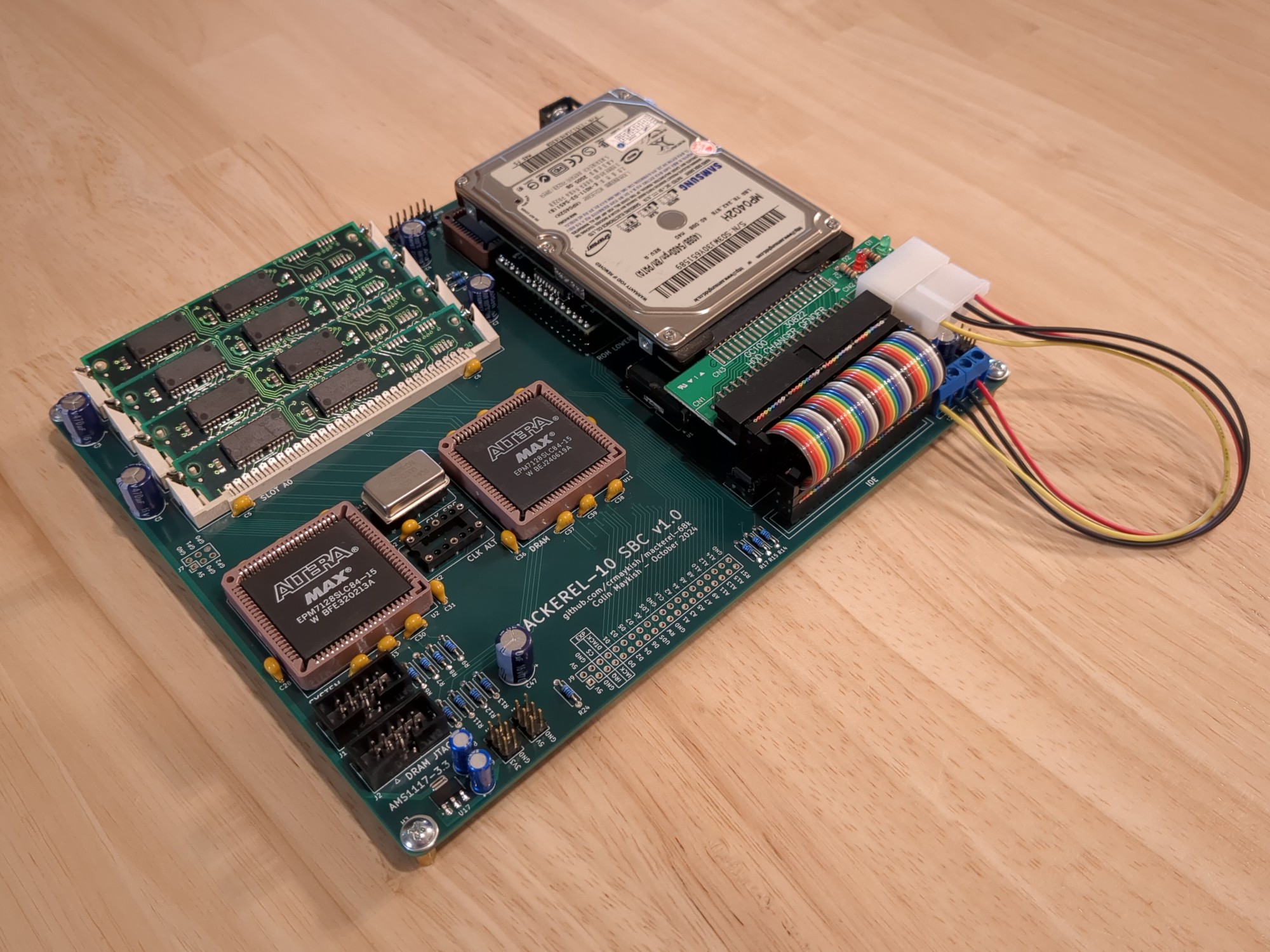
The first round of PCBs for the Mackerel-10 SBC are in and I've begun assembly and board bringup. There aren't too many software changes going from the prototype to v1, but the hardware changed a little bit. There are now four 30-pin SIMM slots instead of two. These are arranged in two pairs to allow a 4x4MB DRAM configuration. Additionally, the IDE interface is now buffered through a set of 74HC245 chips to handle longer ribbon cables. The upper and lower bytes of the 16-bit IDE interface are also swapped in the layout to transparently convert the IDE little-endianness to the 68k's big-endianness. Finally, the pinouts of both CPLDs were completely changed to facilitate the routing of this board, so all of the pin mappings had to be updated in the Verilog projects.

The core system (CPU, ROM, SRAM, DUART) came up pretty quickly once the glue logic and memory map was updated. The DRAM controller also works as expected. I had to update the DRAM controller to handle the extra two SIMM slots, but Mackerel-10 now has access to 14MB of DRAM. One megabyte is still used by the SRAM and the ROM and I/O share the remaining megabyte of address space. All in, that means we've now got 15MB of usable RAM on board.
My DRAM controller is currently running fairly slowly (12.5MHz) at twice the CPU clock frequency (6.25 MHz). I added a second oscillator to the CPLDs with the hope of running the CPU and the DRAM controller on independent clocks, but I have not spent any time working on this. Ideally, the DRAM controller runs at whatever maximum frequency it can without having to worry about being in sync with the CPU clock. Since the DRAM bus access is asynchronous using its own DTACK signal, this should be possible, but I'll need to do some experimentaton and timing analysis.
The new IDE interface caused me some trouble. In the prototype, the 16-bit data bus from the CPU was wired directly to the IDE drive. Adding buffers between them will help with stability and lighten the load on the CPU data bus, but it adds a little more complexity and enough room to screw something up, which I did. After a lot of debugging with the oscilloscope, I realized the buffers are working fine, but the direction pin was inverted (or the A and B buses on the buffers were inverted, depending on your perspective). This meant the buffers were always pointing the wrong direction when the CPU tried to access the IDE registers. This was a dumb mistake I made in the schematic, but I was able to fix it by cutting the trace from the RW pin to the DIR pins on the buffers and creating the proper direction signal from one of the spare CPLD pins. With this bodge in place, IDE was functioning again.

There is minimal software support for IDE devices at the moment, but Mackerel-10 can read and write arbitrary sectors from the disk and print out drive identification info. I've done most of my testing with a SD-to-IDE adapter for simplicity, but I wanted to hook up a real IDE hard drive to make sure that was also working.

I'm a little disappointed about the IDE bodge, but I'm really pleased with the overall SBC. There are a few other minor issues with the v1 design that I will address in a future PCB revision, but my focus will now turn back to the uClinux port. I have a lot more RAM to play with and a real IDE device opens up a lot of options, at least once I figure out how to write a driver for it.
 Colin
Colin
Discussions
Become a Hackaday.io Member
Create an account to leave a comment. Already have an account? Log In.