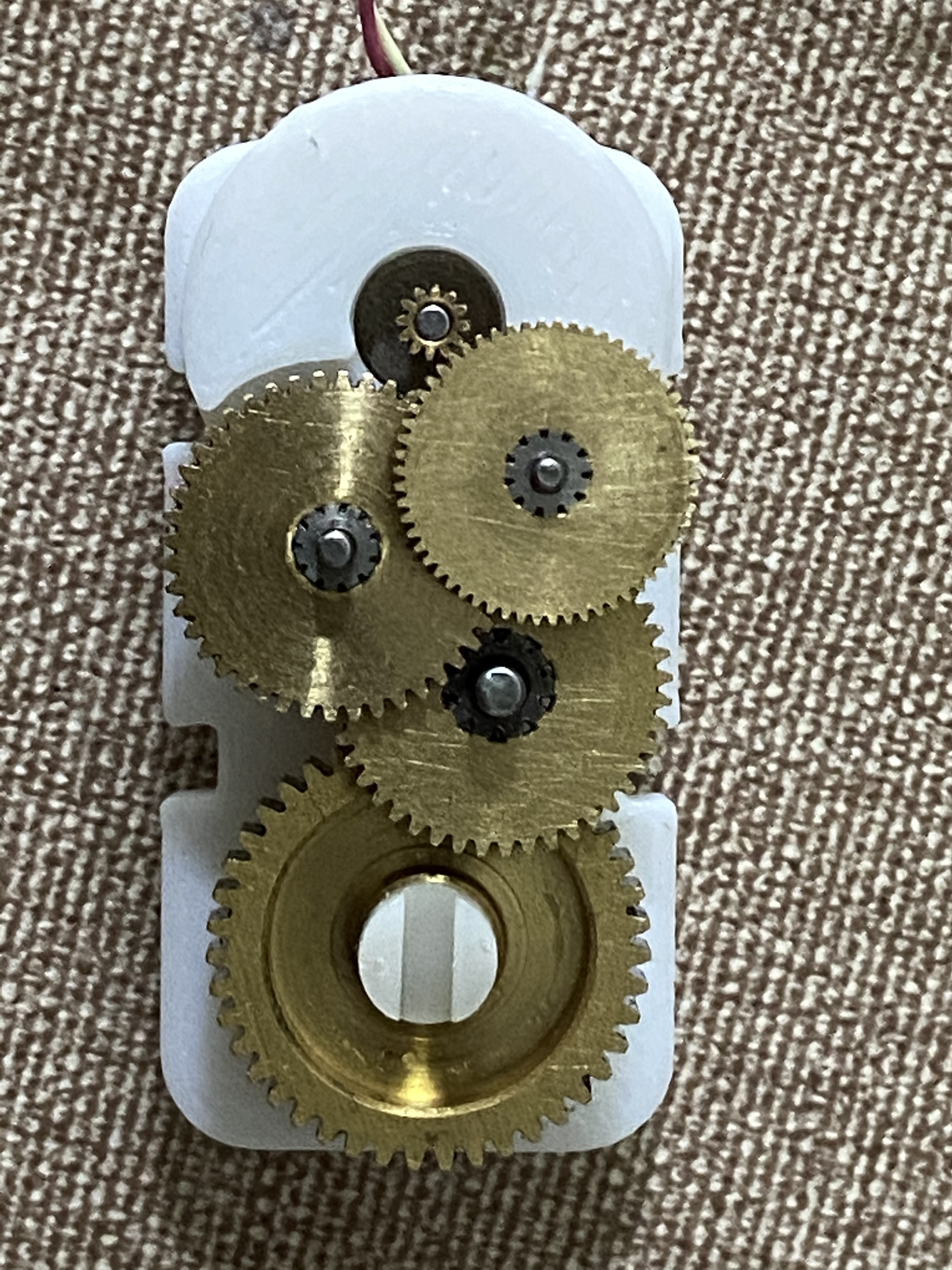
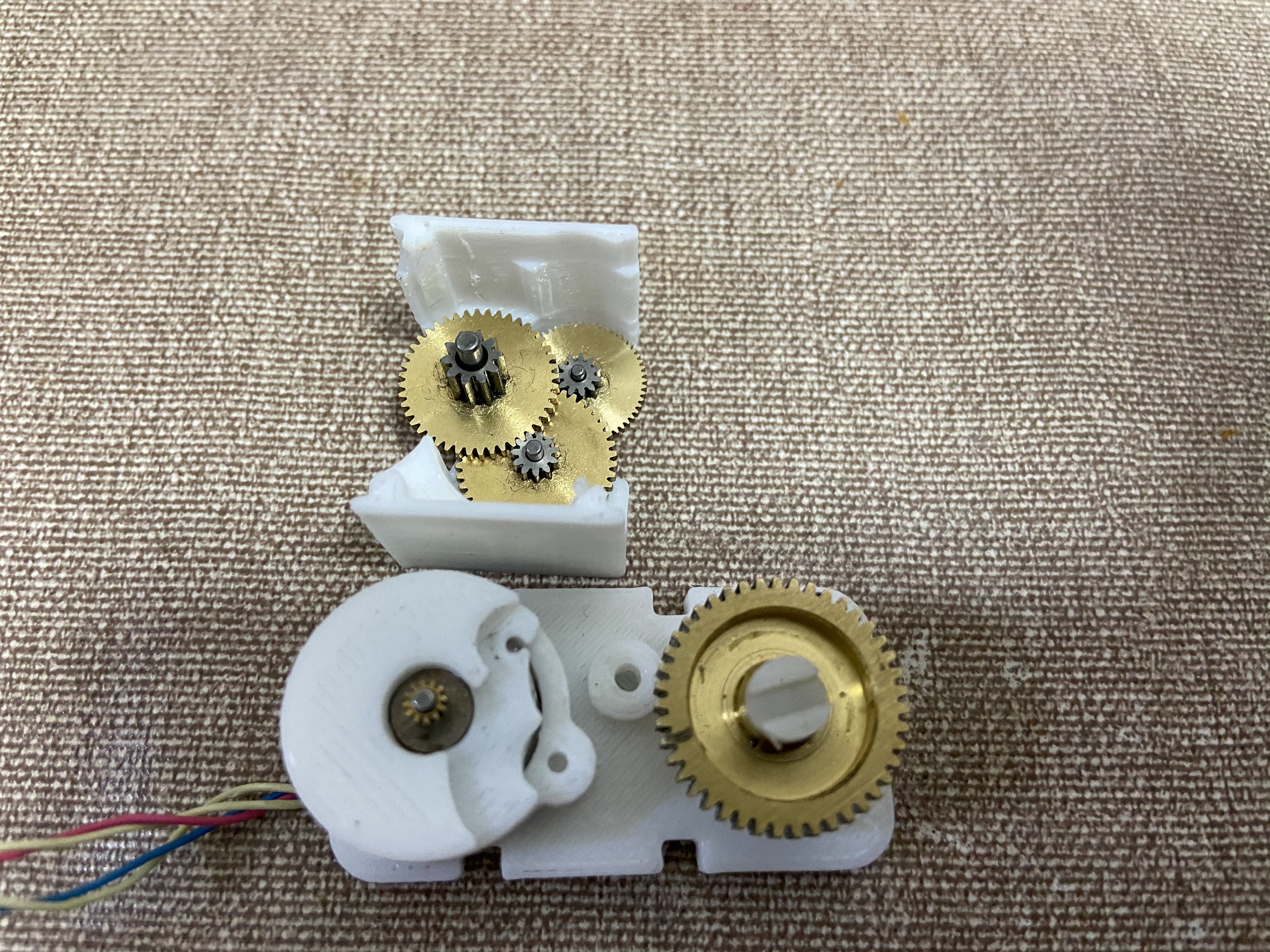
The clock consists of the tops arms and the bottom base. The long arm contains 2 stepper motors, The arduino and the stepper drivers. The Stepper motors although being small consist of a gearbox pulled out of big servo motors. This gives them enough torque to lift the arm . Motor - A is directly linked to pivot of the small arm and rotates it directly. Motor - B is rotates the bottom drum which is linked with belts to the central drum and top arm. If the arm is anchored with the bottom drum then the arm rotates about the bottom drum .When it is anchored to the top drum the arms pivot around the bottom drum via the belts. The arms can anchor to the top, center and bottom drums depending on what kind of movement is required.
The drums have a small magnet mounted on the pivot . The angle of the magnet is sensed using a As5600 rotary sensor which gives the angle feedback to the arduino about the arm location . This avoid unnecessary crashes into the base.
The base consists of two servos which act as the anchors to the arms as well as provide power to the arm. The servos consist of two metal hooks which power the arms with copper clips in the top bottom and center drums. The arms and the base communicate wirelessly using nrf24l01 radio modules. The arms contain the master arduino which does the heavy lifting and sends command to the base to open or close as needed.
The tricky part was power distribution though rotating joints. The power is run though diy slip rings and brushes on every rotary joint. Developing reliable ones out of copper strips and 3d printed parts was a major PITA.
Another big problem is error handling in case when the arms don't anchor properly. This one is something I am still working on. The anchoring is a bit unreliable and sometimes the arms crash and halt the clock completely. The drums are not very durable and cannot take the repeated abuse of closing and opening and need to be ideally out of aluminum .That is next target
base lock unlock :

 ekaggrat singh kalsi
