 suikale
I modified the test code to work with an Attiny85
#include <avr/io.h>
#define ANT_PIN PB3

int main(void)
{
    // set ANT_PIN as output
    DDRB |= (1 << ANT_PIN);

    for (int i = 0; i < 10000000; i++)
    {
        PORTB |= (1 << ANT_PIN);  // high
        PORTB &= ~(1 << ANT_PIN); // low
    }

    return 0;
}
I flashed the IC with Raspberry Pi, and captured about 30 seconds of data from the antenna pin.
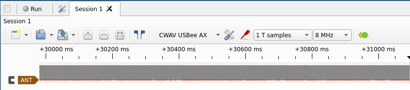
Analyzing a few million lines from the captured data shows all of the state changes are now between 1 and 3 microseconds. There is a bit of fluctuation but less than the original remote has
$ cat attiny.txt | awk '{if ($2 > 3) {print $0}}' | wc -l
0

$ cat attiny.txt | head -n 10
time:    2.875000 µs, state: 0
time:    1.375000 µs, state: 1
time:    2.750000 µs, state: 0
time:    1.375000 µs, state: 1
time:    2.875000 µs, state: 0
time:    1.375000 µs, state: 1
time:    2.875000 µs, state: 0
time:    1.375000 µs, state: 1
time:    2.750000 µs, state: 0
time:    1.375000 µs, state: 1
After changing a few lines from the main code I could capture the "1 ON" -signal. It looks exactly like from the original remote. After switching the logic analyzer for an antenna it turns on the plug every single time
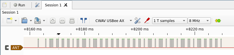
Now it's time to write some code to make the IC behave more like a remote control rather than spamming just one signal
Discussions
Become a Hackaday.io Member
Create an account to leave a comment. Already have an account? Log In.